© Edwards Limited 2012. All rights reserved. Page iii
Edwards and the Edwards logo are trademarks of Edwards Limited.
Contents
A705-61-880 Issue M
Illustrations
Figure Page
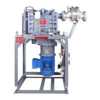
1 The GV pump ............................................................................................................. 2
2 Pump dimensions ........................................................................................................ 9
3 Schematic diagram of the recommended electrical connections ...............................................15
4 Connect to the thermal snap-switches ..............................................................................18
5 Exploded view of the gas-ballast assembly .........................................................................23
6 Exploded view of the gas-ballast air filter ..........................................................................30
7 Exploded view of the interstage relief valve .......................................................................31
8 Oil-level sight-glass and oil filler and drain ports .................................................................34
9 Relubricate the high vacuum bearings ..............................................................................35
10 Exploded view of the pump-motor, coupling drive and coupling housing .....................................40
Tables
Table Page
1 Operating and storage conditions ..................................................................................... 5
2 Performance data ........................................................................................................ 5
3 Materials of Construction ............................................................................................... 6
4 Mechanical data .......................................................................................................... 6
5 Electrical data ............................................................................................................ 7
6 Cooling system data ..................................................................................................... 7
7 Lubrication data ......................................................................................................... 8
8 Shaft-seals purge system data ......................................................................................... 8
9 Connections data ........................................................................................................ 8
10 Noise data ................................................................................................................. 8
11 Checklist of items .......................................................................................................12
12 Maintenance plan .......................................................................................................28
13 Recommended frequencies for high-vacuum bearing relubrication ............................................33
14 Motor relubrication grease required .................................................................................42
15 Motor bearing relubrication intervals ................................................................................42
16 Fault finding .............................................................................................................43
17 Spares Item Numbers ...................................................................................................48
18 Accessory Item Numbers ...............................................................................................48

 Loading...
