EASZ-2 Manual v1.12 - 12.2.2018 Page 12 / 30
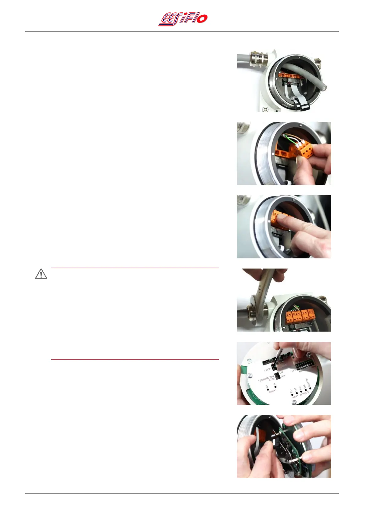
7) To make cable access easier remove all the orange
connector blocks.
8) Pass the incoming (and outgoing if used) cable through the
gland ensuring to leave a loop on the outside to avoid
running water into the unit, otherwise the IP certification
could be at risk and this will invalidated the warranty.
If the unit is mounted vertically then only use the bottom
gland and place a plug in the top position.
9) Strip and crimp the wire ends ensuring that the wires are
connected securely with no loose strands.
10) Connect the wires to the correct terminal blocks using a
screwdriver to lift the spring clip.
11) Once all the wires are connected correctly according to the
required connection option press the connectors firmly
back into their sockets to ensure a positive fit.
12) After all the connections are made all the glands must be
correctly tightened using a spanner. Take care not to
damage the cables by over tightening the glands.
When using EASZ-2Ex, all unused cable glands must be
removed and replaced with special Ex plugs.
The body of the Unit is a flameproof enclosure and it is
essential that all glands and plugs are correctly tightened to
the manufacturer’s torque settings, otherwise the certification
could be at risk, and the Ex protection could be compromised.
The cable glands supplied are NPT ¾” HSK-Ex-D and should
be correctly tightened to a torque of 30 Nm.
In the event that the cables or glands are found to be
damaged they must be replaced immediately.
13) Configure the unit by setting the correct DIP switches on
the back of the display board according to the required
connection option.
Current Loop – Active or Passive
RS485 Termination resistor – On or Off
RS485 ModBus Address
14) Reconnect the ribbon leads to the back of the display
board.
 Loading...