EASZ-2 Manual v1.12 - 12.2.2018 Page 17 / 30
GND
B
A
OUT
IN
- +-
POWER RS 485 LOOP OPEN
+
R 470
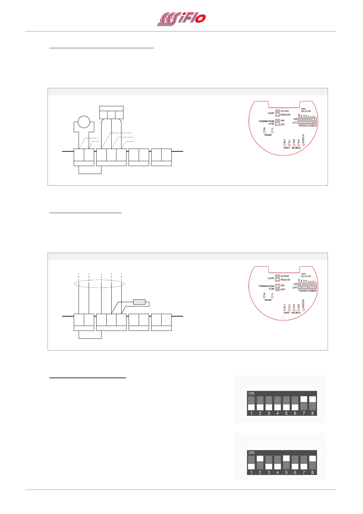
4.8.5. RS485 (Modbus) Interface Connection
Connect the power supply to the “Power” terminals and the RS485 interface to the noninverting (A) and
the inverting (B) terminals using 5-core cable. Both the power supply and the RS485 interface can be
connected as a single cable or as a through connection to another unit.
RS485 – Modbus (wired in series)
GND common internally
RS 485 can be wired
in series
Loop: PASSIVE
Termination: OFF
Modbus: SET ADDRESS
4.8.6. Set a Termination Resistor
The end of the RS485 bus must be terminated with a termination resistor either by adding a 470 Ω resistor
between the (A) and (B) terminals on the RS485 connector block OR a termination resistor can be
connected internally by switching the “Termination 470R” DIP switch ON.
RS485 – Modbus Termination (end of series)
add a 470 Ω resistor between (A) (B)
OR
set “Termination” DIP ON
Loop: PASSIVE
Termination: ON
Modbus: SET ADDRESS
4.8.7. Setting the Modbus Address
Set the Modbus communication address using the “MODBUS”
DIP switches on the right. The address is the sum of the “ON”
DIPs. The address range is 1 – 255.
Examples of Modbus addresses:
To set Modbus address is 3 = set DIPs 2 + 1 ON
To set Modbus address is 73 = set DIPs 64 + 8 + 1 ON
GND
B
A
OUT
IN
- +-
POWER RS 485 LOOP OPEN
+
+
11...28 Vdc
=
RS 485
AB
GND
 Loading...