Note: 9-pin male connector assembly
is included (replacement part # 7154).
]
]
5-24 VDC
250 mA Max
5-24 VDC
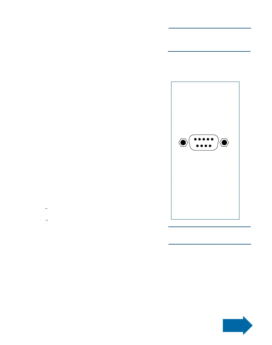
Pin Function
1. Initiate +
2. Initiate -
3. Output +
4. Output -
5. Contact Closure
6. Chassis Ground
7. Contact Closure
8. Not Used
9. Not Used
I/O Connection
The 9-pin D connector
and internal circuitry pro-
vide external initiate and
end-of-cycle feedback sig-
nal. The pin connections
are shown below.
18 / Input / Output
Connections
Input/Output Connections
1. Voltage Initiate Circuit
The VALVEMATE
™
7040 may be initiated with a 5 to 24
VDC signal across pins 1 and 2. The signal can be
momentary (no less than 0.02 seconds) or maintained.
A new cycle will begin once power is removed and then
applied again. Refer to the schematic on page 19 for
proper installation.
2. End-of-Cycle Feedback Circuit
Upon completion of a dispense cycle, an open collector
circuit closes and remains closed until the next dispense
cycle. This circuit can be utilized to signal back to a
host computer, start another device in sequence or
other operations that need to be tied into completion of
the dispense cycle.
Upon closure, power from an external 5 to 24 VDC
source is allowed to pass through the circuit to operate
a load. The load illustrated is a relay, but this could be
any device that will operate within the 5 to 24 volt range.
Power consumption of the load must not exceed 250
mA.
3. Mechanical Contact Initiate
The VALVEMATE
™
can be initiated via the closure of
me
chanical contacts such as a relay or switch using pins
5 and 7. Closure of the contacts can be momentary (no
less than 0.02 seconds) or maintained. A new cycle will
begin once the contacts are opened and then closed
again. Refer to the schematic on page 19 for proper
installation.
Note: For applications using more
than one 7040, see page 20 for con-
nection instructions.