Connecting more than one 7040 Controller
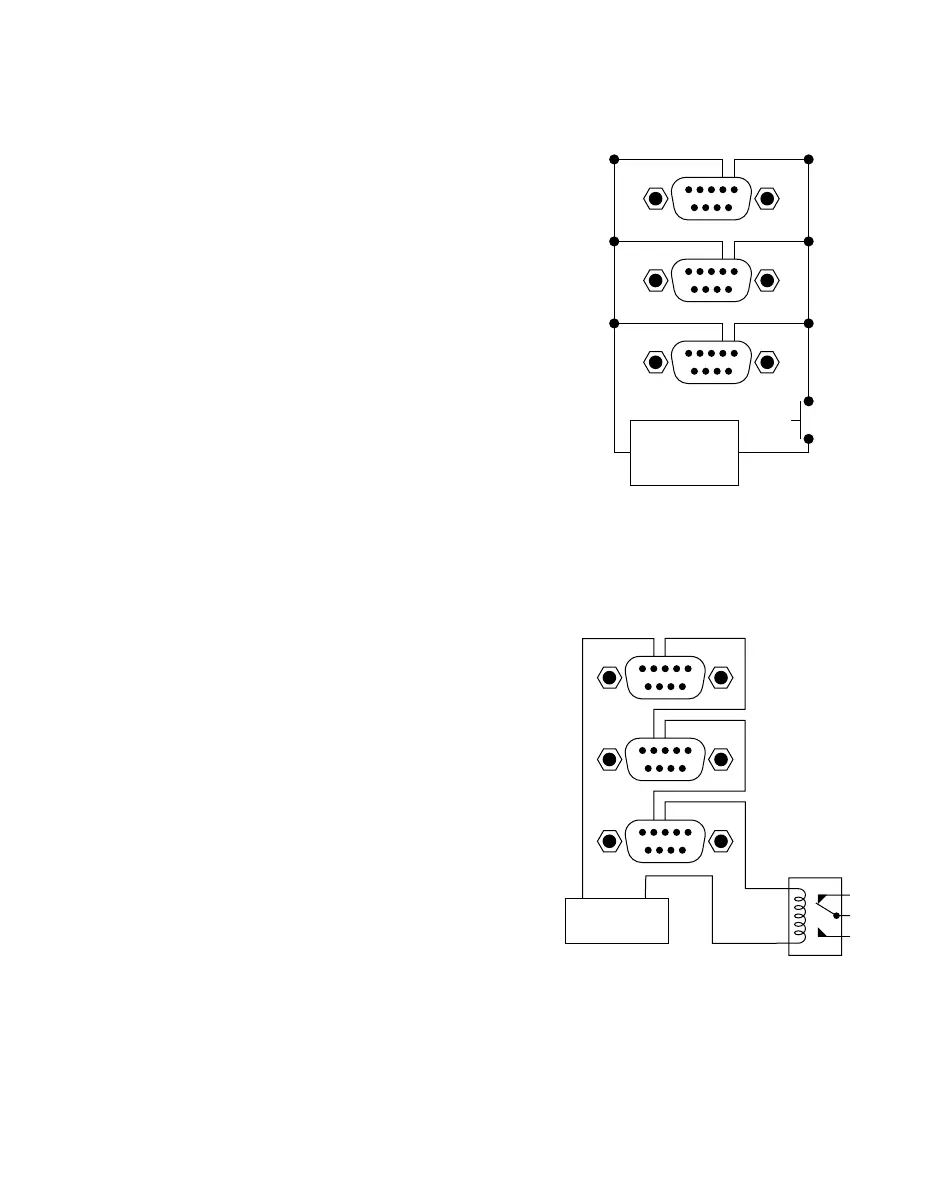
2. Series circuit for End-of-Cycle Feedback
feature. A relay is illustrated as one example
for utilizing the feedback circuit.
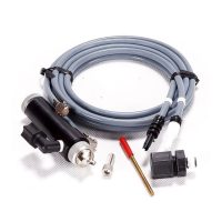
1. Parallel circuit diagram for Voltage Initiate.
20 / Connecting More Than One 7040 Controller
Follow these instructions and diagrams when the
Voltage Initiate or End-of-Cycle Feedback features are
used in a multiple 7040 installation.
1. Voltage Initiate Circuit
To start the dispense cycle for multiple 7040's at the
same time, connect the Voltage Initiate Circuit in paral-
lel as illustrated.
Note: The amperage consumption for the Voltage Initiate Circuit
will increase with each VALVEMATE
™
7040 that is connected.
The initiate power supply should be sized accordingly.
Example: First 7040 consumes 15.0 mA at 24 volts.
Second one will consume another 15.0 mA; total now is
30.0 mA. Third one will consume another 15.0, making
the total 45.0 mA and so on.
2. End-of-Cycle Feedback Circuit
This circuit will ensure that the End-of-Cycle signal will
come from the last 7040 to complete a dispense cycle.
Connect in series as illustrated.
Note: There will be a maximum voltage drop of 2.0 VDC through
the Feedback Circuit with each 7040 that is added to the series.
The input power should be adjusted for this drop to ensure that
the required voltage is available to operate the load. Maximum
input voltage to terminals 3 and 4 must not exceed 30.0 VDC.
Example: The device to be controlled through the
Feedback Circuit operates at 12 VDC. Four 7040's are
to be used. 4 x 2.0 = 8.0 VDC drop. Power supply
should provide (12.0 + 8.0) or 20.0 VDC to ensure that
12.0 VDC is available to run the load.
REMEMBER: Maximum current through the Feedback Circuit
must not exceed 250 mA.
6789
12345
6789
12345
6789
12345
5-24 VDC
Source
+
-
6789
12345
6789
12345
6789
12345
+
_