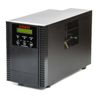
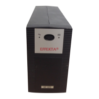
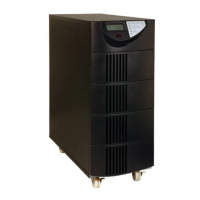
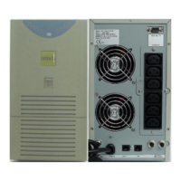
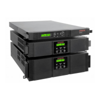
UPS: MKD 700 – 3000 VA RT (XL) UPS Device Description
3. UPS device description
This UPS device is an ONLINE UPS after the double conversion principle.
Based on the outstanding performance according to EN 62040-3, the UPS
receives “Class 1” (VFI-SS-111) classification. This way subsequently
connected appliances will be optimally provided for, irrespective of how a
primary source of power (mains power supply) performs.
Malfunctions such as: mains power failure, power supply undervoltage, power
supply overvoltage, temporary mains voltage changes (transients), subtle mains
power deviations, frequency changes, etc. will not be transferred to the
connected loads in standard operating mode.
The UPS is used to support sensitive devices and facilities such as, e.g.:
computers, servers, emergency systems, electronic cash registers, instruments
critical to operation critical, telecommunication facilities, processor control
systems, surveillance and management systems, etc.
A conversion to autonomous time follows by way of the adaption of an external
battery bank or its capacity.
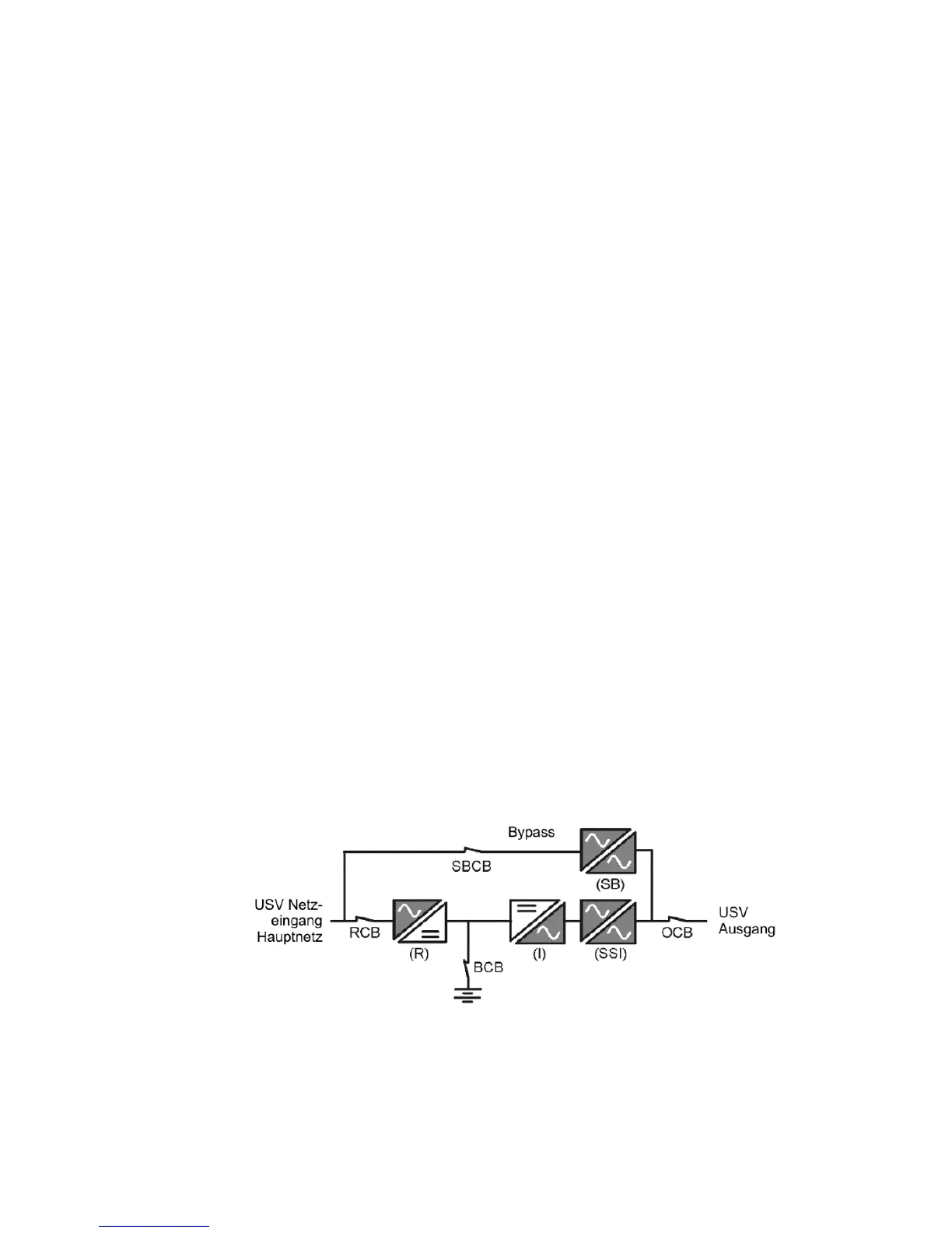
3.1 Topology and operating modes
The following figure (
Fig. 3-1), a block diagram of the UPS device, clearly shows the double
conversion principle. The mains power supply is converted to the DC
intermediate circuit whereby the energy storage (battery bank) is charged. The
loads, or appliances, on the UPS output are fed without failures or interruptions
by an additional conversion (INVERTER).
Fig. 3-1 Topology, function groups for the UPS device.
It is clear that, within the mains power supply, failures do not reach the UPS
output and, consequently, the load. Furthermore, all operation modes of the
UPS device can be derived from and represented by the above mentioned block
diagram: