EN‐24
MA510a_EN
Instruction’sManual
INSTALLATION
Inspecttheunitfordamagesduringtransport.Theclaimsforpossible
damages will be accepted only in case they are immediately
communicated to the carrier; the damages that are found must be
writtendownand presentedtomanufacturerortoyourownretailer.
Iftheunitisreturnedtothemanufat
urerortoyourownretailer,itis
necessary to use the original equipment’s package or another
equivalentone,toguaranteethesafetyduringthetransport.
Unpack the equipment and carefully study the documentation and
operating instruction supplied. Mains voltage, indicated above the
inlet, must agree with the local mains voltage (mains voltage
freque
ncy: 50‐60 Hz). The correct voltage (see above) setting is
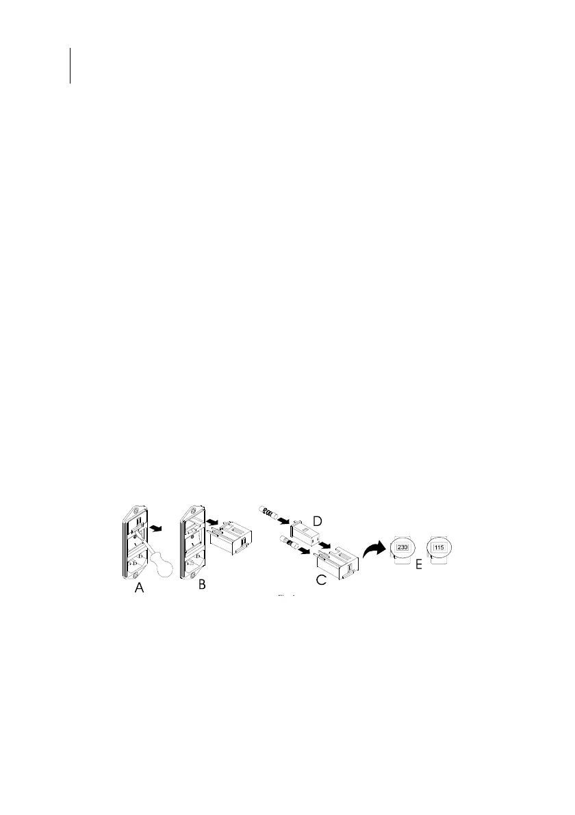
selected as shown in fig. E. Insert the correct fuses in the module
referringtothevaluewrittenonthelabel.
The predisposition of the correct mains voltage is performed in the
followingway:
(A‐B)Extractth
efuseholderdrawerfromthepowermodule.
(C)Insertthefusesmakingreferencetothefollowingchart:
MainsVoltage 110‐120V DelayedFuse2x2xT6,3AL,250V/5x20mm
MainsVoltage 220‐240V DelayedFuse2xT3,15AL,250V/5x20mm
(D)Extractandrotatethedetachablepartinwaytoreadthe
correctvoltageinthe(E)window–reinsertthefuseholderinthe
module.
Connectmainscabletoamainsoutlethavinggoodhearthconnection.
OPERATIONOFTHEEQUIPMENTWITHOUTEARTHCONNECTIONIS
FORBIDDEN.
Theunitmustbeinstalledonalevelsurface,withdimension,atleast,
correspondenttothoseofthebaseoftheunit itself.Aroundtheunit
mustbeleftaspaceof25c
m,atleast.
Connectthemainscabletothemainssocketontherearpanelofthe
unit.
 Loading...