14
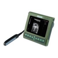
USER MANUAL MAGIC 500 PLUS ULTRASOUND UNIT
T +49 7461 96 580 0 | F + 49 7461 96 580 90 | export@eickemeyer.com | www.eickemeyer.com
The benefi ts of using this method:
• Self-built darkroom for the strong-light environments.
• The protection of the soft leather bag can avoid collisions and pollution in the use process.
5.2 Ultrasonic Probe Installation
Danger!
Do not use together with fl ammable anaesthetic, it may result in an explosion.
Warning!
1. Do not use a probe not provided by EICKEMEYER®, otherwise the equipment and the probe will cause damage,
and may cause fi re in extreme cases.
2. Check the ultrasonic probe and connecting cable after diagnostic operation. Use of a defective probe may
cause electric shock.
3. Do not strike the probe; using a damaged probe may cause electric shock to the patient.
4. Unauthorized disassembly of the probe is prohibited as it may cause electric shock.
Attention!
1. Turn off the ultrasonic system before disconnecting the probe. Disconnecting the probe with system power on
may damage the system or probe.
2. Before disconnecting the probe, place the cable and probe on a stable and leveled position so that the probe
may not be damaged or injury person by unexpected fall.
3. Freeze the instrument when instrument is start-up without operation to increase of service life of probe.
4. Repeat available machine time should be more than 5 minutes to avoid turn on / off power supply in short
time.
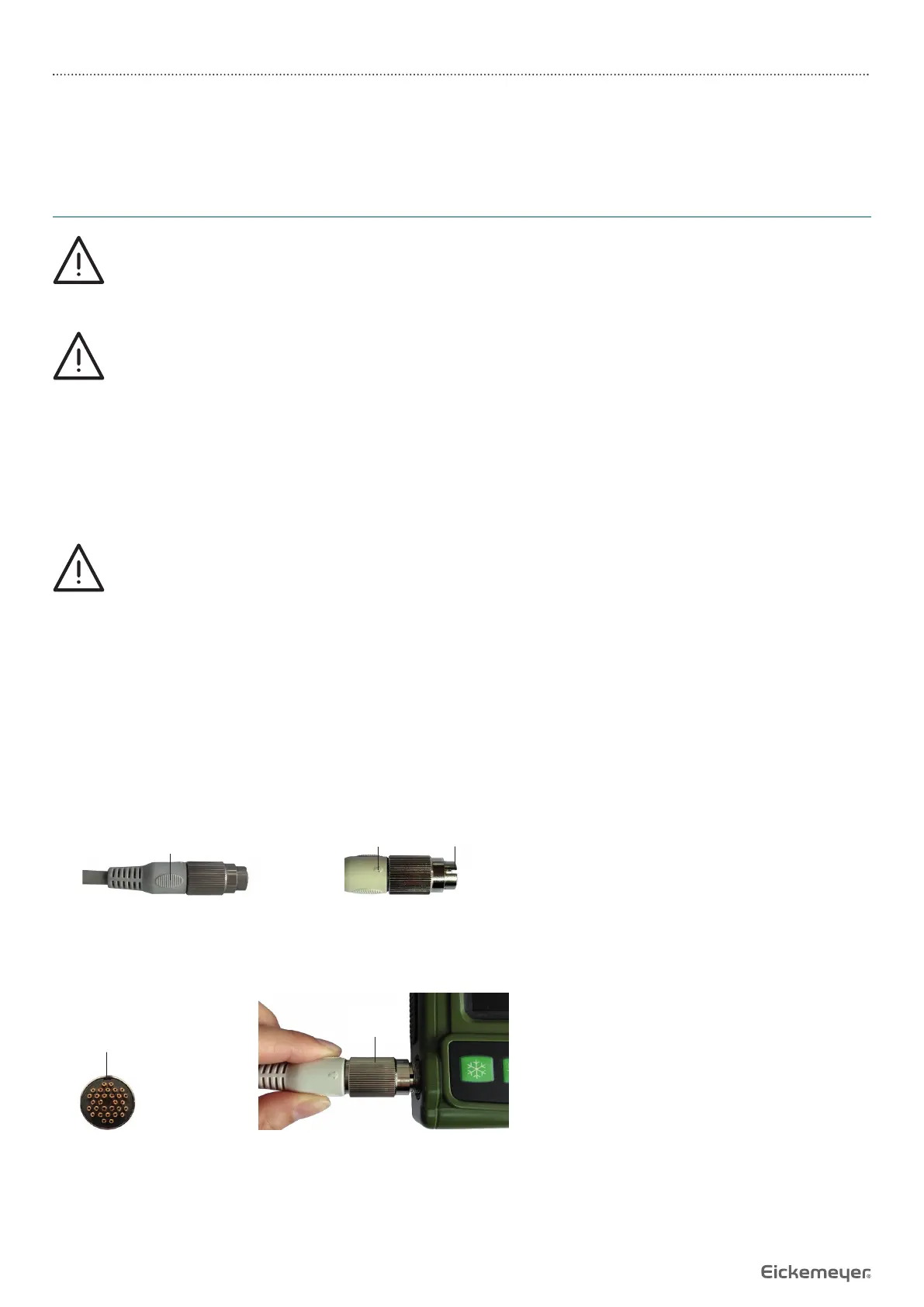
5.2.1 Ultrasonic Probe Connection
1. Turn off the system, pinch the oval position on both sides of the probe cable while keeping the arrow above, as shown.
Pinch here
Arrow direction Notch
2. As shown below, insert the probe connector horizontally into the probe socket labeled “PROBE” on the left side of the
main unit. When inserting the probe, the notch on the probe connector should be aligned with the position of the
protruding mark on the probe interface, and push the probe fi rmly into the probe socket of main unit.
Protruding marker
position
Knob