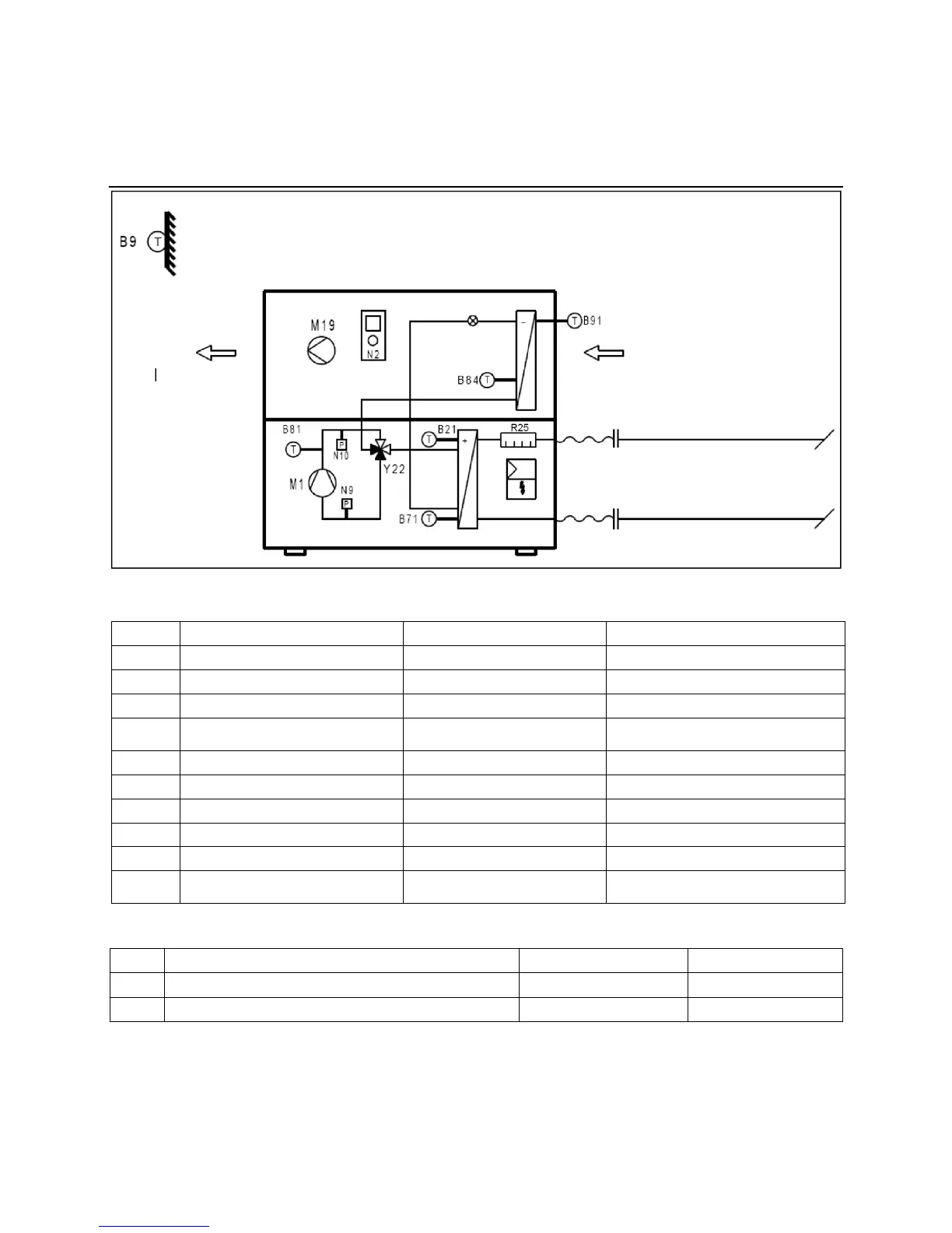
Air in
Flow sensor
Return sensor
Air out
Electrical Connections
Unit Design, Terminal Assignment
AEROTOP T..
Description RVS61 Slot RVS61 Output
N9
Low pressure K E9
N10
High pressure K E10
Y22
Process reversal valve Y22 W QX1
R25
Electrical heater element 1 flow
(only with AEROTOP T07 to T16)
W QX2
B81
Hot gas temperature sensor 1 f B81
B21
Heat pump flow temp. sensor n B21
B71
Heat pump return temp. sensor q B71
B91
Source intake temp. sensor r B91
B84
Evaporator temp. sensor s B84/B92
M19
Fan z (AEROTOP T07-T16)
U (AEROTOP T20-T35)
UX (AEROTOP T07-T16)
Q8-K19 (AEROTOP T20-T35)
Controller terminal assignment of components wired at the factory:
Please consult the electrical diagram of the heat pump for complete terminal assignments and electrical connections.
Description RVS61 Slot RVS61 Output
Q9
Condenser pump V Q9
B9
Outdoor temperature sensor k B9
Other important components to be wired in the system
11
 Loading...