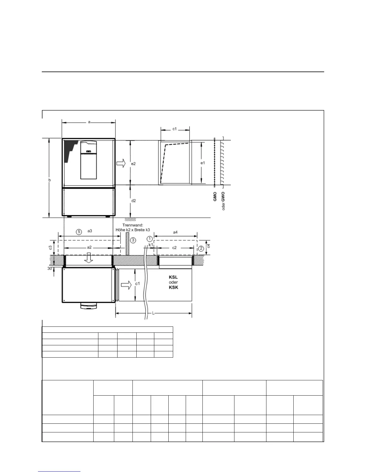
Indoor Installation
Parallel Setup with Rigid Duct
24
Required Accessories:
• AIR IN wall setup kit
• AIR OUT parallel installation with
rigid duct.
All dimensions refer to a
finished floor and completed
walls/masonry.
Light well dimension
a3 a4 c3 c4
T07C, T07 1200 800 600 600
T10C, T10 1200 1000 600 600
T12C, T12, T14, T16 1200 1000 600 600
AEROTOP T
Rigid Duct
Dimension
Cutouts without Insulation
Distance between
Cutouts
Partition Wall
e1 c1 a2 c2 d2 e2
k1 without
partition
wall
k1 with
partition
wall
Height k2 Width k3
T07C, T07 800 520 950 600 640 860 1500 630 1500 1000
T10C, T10 850 620 1050 700 640 910 1500 630 1500 1000
T12C, T12, T14, T16 950 620 1150 700 640 1010 1800 630 1700 1200
Light well
Light well
1) The compliance with acoustic
limit values must be clarified by
customer.
2) Necessary outside insulation by
customer, minimal clearance of
light well must not be gone below.
• Attach flex sleeve (A) to inside
frame of unit.
• Attach sealing tape to sheet metal
duct on the side that is attached
to the sleeve.
• Insert the sheet metal duct into
the cutout. The sheet metal duct
may not touch the wall in the cutout
at any side. This can be achieved
by placing a piece of insulation into
the center of the cutout.
• Use the enclosed screws to affix
sheet metal duct to the sleeve.
Attach the section clips (included
in installation kit) along all sides
between sheet metal duct and
sleeve. This ensures a tight
connection.
• Use insulating foam in between
the gaps of the cutout and the
sheet metal duct from the outside
of the cutout. An opening in the
sheet metal duct makes it possible
to insert the nozzle of the spray
can. Completely fill the area
between duct and cutout with foam.
• Mount air intake cover grating
on exterior wall. Select either a
mesh, protective grating, or a
sound-dampening protective
3) Possible air short-circuit to be
prevented by customer; for the
short duct (KSK) it is necessary
to apply a partition wall.
5) Noise level of AIR OUT and AIR IN
must be considered separately
 Loading...