Man. NVIP3 – Rel 1.3 EN (UK)
- 20 -
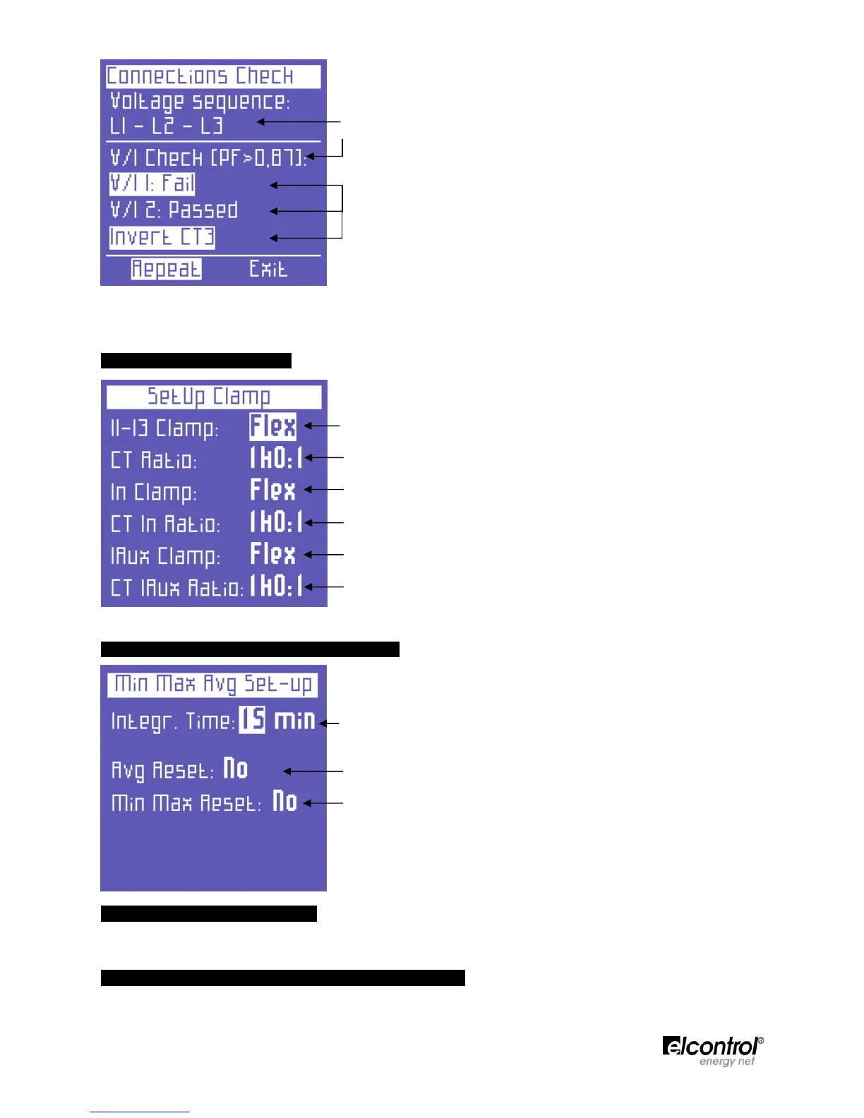
• Voltage phase sequence
• Threshold of the measured PF which allows for a correct analysis (if
the PF is lower than the value indicated, the check cannot provide
valid information)
• Check of the correspondence between voltage and current of each
phaseand possible error message:
Ok = Connection is correct
Invert CT = Invert the direction of the current clamp
indicated
Failed = No correspondence between voltage and current
or the PF value is lower than the threshold displayed
Select "Repeat" to perform a new check.
Select "Exit" to return to the CONNECTIONS SETUP page.
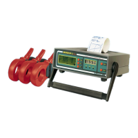
4.2.2 - Current Probes Setup
This page allows the user to select:
● the type of probe used for I1, I2, I3, i.e. Flex (non-amplified
flexible sensors) or AC/DC (clamp);
● the sensor transformation ratio on I1, I2, I3 (press and hold down
or to increase scrolling speed);
● the type of probe used for In, i.e. Flex (non-amplified flexible
sensor) or AC/DC (clamp);
● the sensor transformation ratio on In (press and hold down or
to increase scrolling speed);
● the type of probe used for Iaux, i.e. Flex (non-amplified flexible
sensor) or AC/DC (clamp);
● the sensor transformation ratio on Iaux (press and hold down or
to increase scrolling speed).
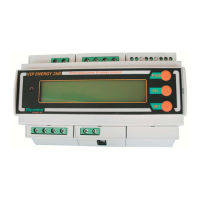
4.2.3 - Minimum, Maximum & Average Setup
This page allows the user to:
● Set the integration time, i.e. the time at which the average values
and maximum demand are calculated.
● Reset the average values and maximum demand.
● Reset the minimum peaks and maximum instant values.
4.2.3.1 - Integration Time Setup
To set the integration time, place the cursor on INTEGR. TIME and select the desired time, which is expressed
in minutes (default value = 15 min).
4.2.3.2 - Reset of Average Values & Maximum Demand
To reset the average values and maximum demand, place the cursor on AVG RESET and select YES.