Man. NVIP3 – Rel 1.3 EN (UK)
- 35 -
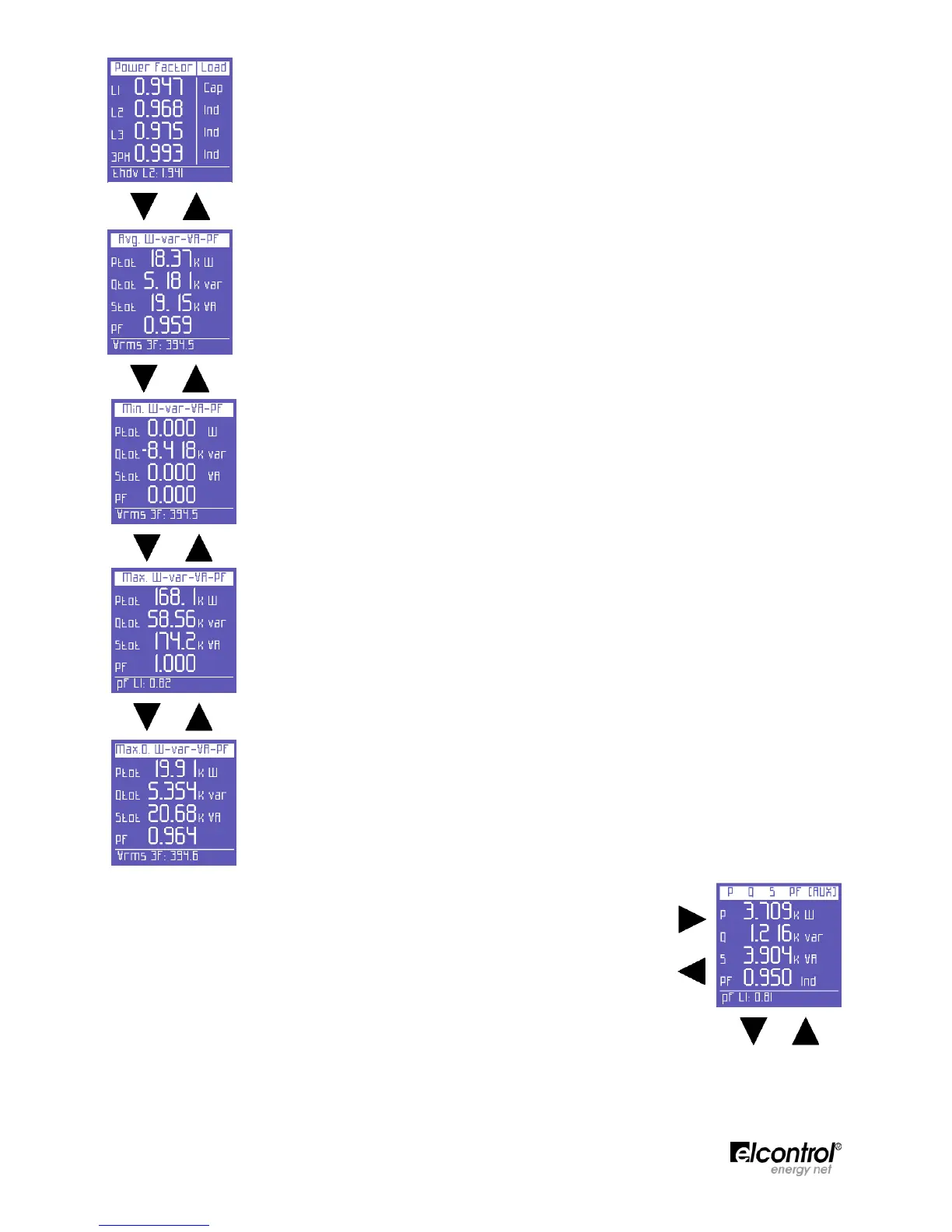
PF values in each phase and in the three-phase (or two-phase) connection and the relevant
type (Ind = Inductive load; Cap = Capacitive load)
NOTE: the PF is always positive. As a norm, it is shown as a negative when active power is
generated and a positive when absorbed.
Average total power and PF (calculated on the basis of the integration time set. Values can
be reset as described in Sect. 4.2.3).
Minimum instant values of total power and PF (values can be reset as described in Sect.
4.2.3.3)
Maximum instant values of total power and PF (values can be reset as described in Sect.
4.2.3.3)
Load peaks and relevant PF, i.e. the highest average power (calculated on the basis of the
integration time set. Values can be reset as described in Sect. 4.2.3.2)
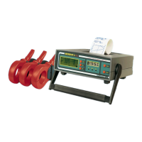
On any of the Power Menu pages, press to access a series of pages containing
all the information regarding auxiliary channel power. The first page displays
active, reactive and apparent power, as well as the PF. Use and arrows to
scroll through the pages (See below). In the AUX Menu, the user can also access
the other Auxiliary Channel Menus (Voltages, Currents, Counters, Harmonics,
Waveforms), by selecting them with the relevant function keys.
Press ⊳ to exit the Auxiliary Menu and return to the first page of the relevant
menu.