34
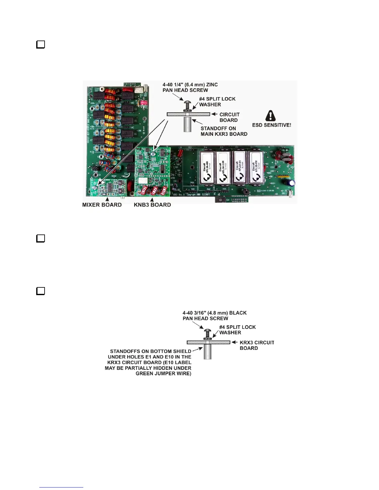
Mount the Mixer and KNB3 boards on the main KRX3A board as shown in Figure 39. Be certain the
connector on each board is properly aligned and mated with the connector on the main KRX3A board. The
boards should be parallel to the KRX3A board. If they are tilted, check to ensure the correct number of washers
were installed under the standoffs and that you used the correct standoffs as shown in Figure 37.
Figure 39, Main KRX3A Board Ready for Installation.
Place the KRX3A main circuit board in the bottom shield so that the 1-1/2” screws extend through holes E7
and E13 on the KRX3A board. The two standoffs you mounted earlier should line up with holes E1 and E10 in
the board. Press the KRX3A main circuit board down against the standoffs. The board will “snap” into position
as the small bumps along the edges of the board slip into the holes in the sides of the shield. If some of the nubs
do not align with the holes in the shield, carefully file them flush with the board so they don’t push the sides of
the shield out of alignment. When properly positioned, the board will be against the standoffs in the shield.
Secure the KRX3A main circuit board to the standoffs at E1 and E10 with 4-40 3/16” (4.8 mm) black pan
head screws and #4 split lock washers as shown in Figure 40.
Figure 40. Mounting KRX3A Main PC Board on Bottom Shield.