42
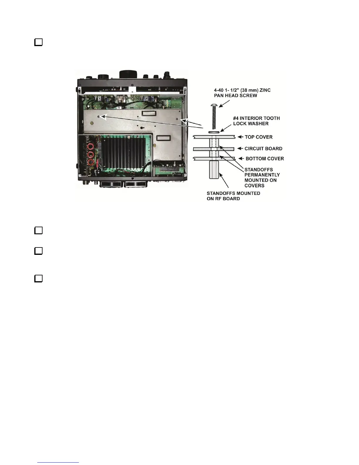
Secure the KRX3A module to the two standoffs using 1-1/2” (38 mm) 4-40 pan head screws as shown in
Figure 50. The screws will pass through the internal standoffs and circuit board inside the enclosure and screw
into the standoffs you mounted on the K3 RF board earlier. Place an inside tooth lock washer under each screw
head.
Figure 50. Installing the KRX3A Enclosure.
Connect a 5” (13 cm) TMP cable between J1 on the KREF3 board and J83 on the Auxiliary KSYN3A
board (see Figure 48).
If you removed the cable between J2 on the KREF3 board and J83 and the Main KSYN3A synthesizer,
replace it now (Figure 48).
Double check all the TMP cables to ensure none were dislodged from their connectors or kinked tightly
while positioning the KRX3A module. The two cables attached to the K3 RF board are not visible, but should
not have been disturbed by installing the KRX3A. Pay particular attention to cables attached to the KREF3 and
KSYN3A boards. If needed, you can replace a dislodged cable without removing the KRX3A module using
needle nose pliers to hold the finger grip part of the connector.