12
Receive Settings
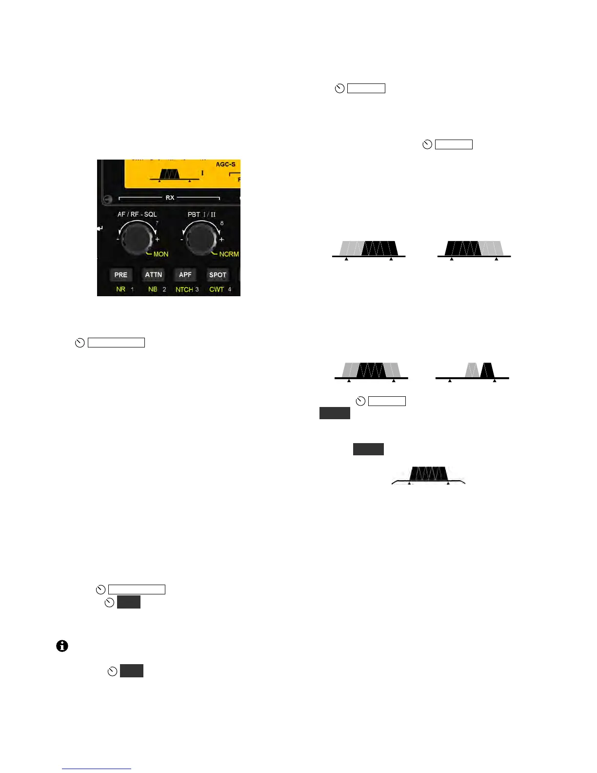
The RX control group, shown below, is used to set
up the KX3’s receiver. Directly above these
controls is the filter passband graphic, which shows
the shape and position of the receiver’s passband.
This determines what pitch range you’ll hear.
AF Gain, RF Gain, and Squelch
The
A F / RF - SQ L knob normally controls
receiver AF gain. Tapping the knob switches its
function to squelch (FM Mode only) or RF gain
(all other modes). Also see “AF, RF, and IF” in the
glossary (pg. 49).
RF gain is normally left at maximum (-0 dB).
Reducing RF gain may be useful in some strong-
signal conditions. If you reduce RF gain more than
a few dB, a separate segment of the S-meter turns
on as a reminder. The segment used varies with the
amount of RF gain reduction. (A high S-meter
reading may hide the RF gain indicator segment.)
Squelch is used to mute the receiver until a signal
appears. It is most often used with repeaters. The
control adjusts the signal threshold required for
squelch to “open,” unmuting the receiver.
Voice Monitor/CW Sidetone Level (MON)
Holding
A F / RF - SQ L temporarily switches its
function to
MO N , which controls how much of
your own signal you hear when transmitting.
Transmit monitor setup is covered on pg. 14.
Switch activation tones, if used, have the same
volume level as the CW sidetone (as set in CW
mode using
MO N ). Switch tones can be set to
off, on, or Morse code characters at various speeds
using the SW TONE menu entry.
Passband Tuning Functions (PBT I/II)
The
P B T I / I I control is used to shape the KX3’s
receive filter passband. In general, a narrow
passband reduces interference (QRM) and noise
(QRN), while a wider passband improves fidelity.
In voice modes, tapping
P B T I / I I selects low-
cut (function I) or high-cut (function II). These
functions remove low- or high-pitched interfering
signals. Examples of filter graphic segments that
might turn off as the result of a low-cut or high-cut
are shown in light gray below.
Low-Cut High-Cut
I
II
In CW and DATA modes, the passband functions
are width (I) and shift (II). The effect of these
functions is illustrated below. Reducing the width
or shifting the passband may attenuate an
interfering signal above or below the desired one.
Width Shift
I
II
Holding
P B T I / I I normalizes the passband
(NO R M ), centering it and setting it to the default
width for the current mode. Two small "anchors"
appear at the left and right ends of the graphic.
Holding N OR M again restores the previous settings.
Roofing Filters (XFIL)
The XFI L icons, to the right of the filter passband
graphic, show whether the optional roofing filters
(FL2 , FL 3 ) are in use. These filters, located on the
KXFL3 option module, can reject strong nearby
signals that might interfere with reception of
weaker ones.
When FL1 is indicated, the roofing filters are
bypassed, and the pre-DSP bandwidth is about 15
kHz. FL2 (3000 Hz) and FL3 (1000 Hz) will be
automatically selected, when possible, based on the
settings of the filter controls.
Dual watch and certain noise blanker settings also
use FL1, overriding the normal per-mode roofing
filter selection.