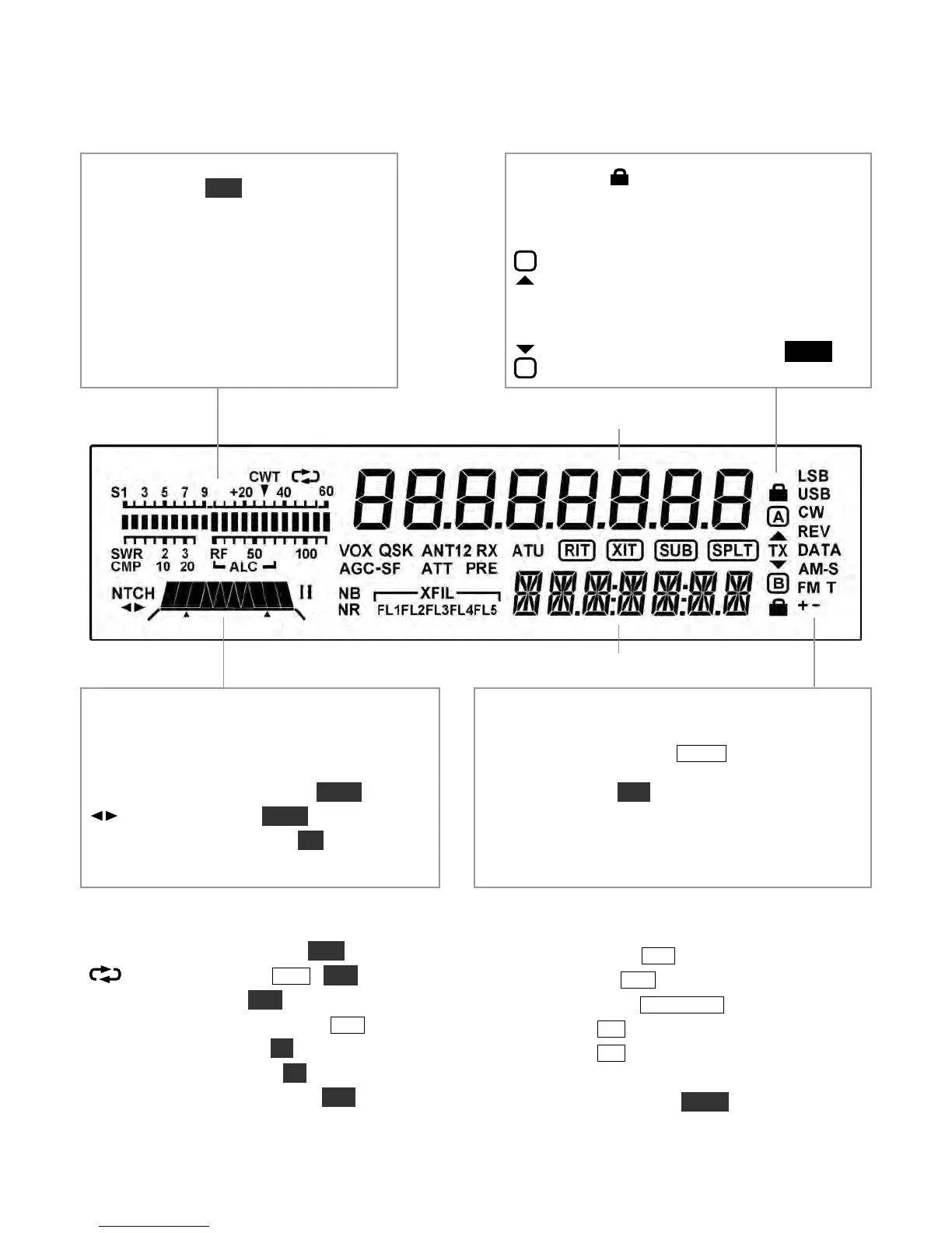
Bar graph, receive mode: Normally acts
as an S-meter. If C WT is turned on, the
right half of the S-meter becomes a tuning
aid (pg. 13). Reducing RF gain adds a
moving reference segment (pg. 12).
Bar graph, transmit mode: Normally
shows SWR and RF output. In voice and
data modes, the bar graph shows CMP
(compression) and AL C whenever mic
gain or compression are adjusted.
VFO Icons: Shows that a VFO or menu
entry is locked. The TX icon points to the transmit
VFO:
VFO A is the transmit VFO
VFO B is the transmit VFO; see
Filter Passband Graphic: Shows location
of receive filter passband (pg. 12)
Filter Icons:
NT C H Auto or manual notch (NT C H, pg. 13)
Manual notch (NT C H , pg. 13)
I / II PBT filter function (I/I I, pg. 12)
XFI L Filter selection (FL1 -FL5 , pg. 12)
Mode Icons
Basic modes (LSB or USB , CW , D AT A , A M, or
FM) are selected by tapping M OD E . Alternate modes
(CW REV, DAT A REV, AM- S, F M +/- ) are
selected by holding AL T . LSB and USB are alternates
of each other. In SSB mode, the + icon indicates
ESSB (pg. 22). T indicates FM PL tone (pg. 15) or
CW/DATA text decode (pg. 19).
Other Icons:
CW T CW/data tuning aid on (C WT , pg. 13)
Message play/rec (M S G / R E C , pp. 16, 21)
VOX VOX enabled (V O X , pp. 15, 16)
QSK Full break-in CW enabled (DL Y , pg. 16)
NB Noise blanker on (N B , pg. 13)
NR Noise reduction on (N R , pg. 13)
AN T Antenna 1/2, KXAT100 (A NT , pg. 25)
RX Automatic RX attenuation in effect (pg. 13)
AT T Attenuator on (A T T , pg. 13)
PRE Preamp on (PR E , pg. 13)
AT U ATU enabled (A T U T U N E , pg. 14)
RIT RIT on (R IT , pg. 11)
XIT XIT on (X IT , pg. 11)
SUB Dual-watch enabled (DUAL RX, pg. 20)
SPL T Split mode in effect (SP L IT , pg. 19)