35
Menu Functions
Hold M EN U to enter the KX3’s menu. Tap or hold this switch to exit. Menu entries that you’d like quick
access to can be assigned to programmable function switches (pg. 19). Note: NO R appears in some parameter
displays. This means “Normal,” i.e. the default or recommended value.
Menu Help Information
Holding ME N U for about 3 seconds while in the menu shows information about the present menu entry on
VFO B. For most entries, the default parameter value is shown in parentheses at the start of the help text. Tap
the switch to terminate the help text display.
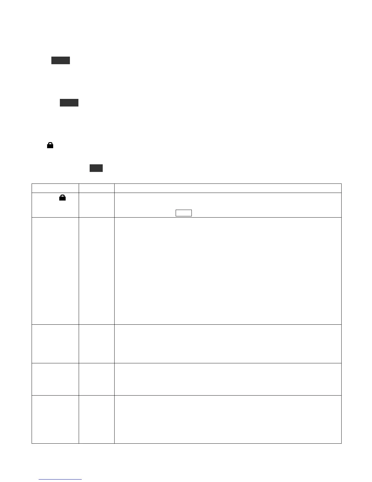
Tech-Mode menu entries
The
symbol
in the table below indicates a tech mode menu entry. These are typically used for calibration,
and their parameter values are locked by default, as indicated by the same lock symbol on the display. To see
tech-mode menu entries, set MENU:TECH MD to ON . To change any tech-mode parameter, you must first
unlock it by holding KH Z for about 3 seconds. This turns off the lock symbol.
Enables built-in 2-tone generator for SSB transmit tests. The internal 2-tone
generator only works if LSB or USB mode is selected. After setting 2-tone ON,
exit the menu and tap XM IT .
Determines the function of the GPIO signal (ACC2 jack, left side panel):
OFF (output, 0 V), ON (output, 3 V), LO=PT T (input; apply 0 V or ground to
activate PTT), HI= PTT (input; apply 3 to 5 V to activate PTT), LO = Inh (input;
0 V inhibits transmit), HI= In h (input; 3 to 5 V inhibits transmit), TR N CTRL
(output; XV-series transverter control using Elecraft auxBus prototcol). If the
GPIO signal is inhibiting transmit, the TX icon will flash as a reminder.
NOTE: External interface circuitry may be required. The GPIO pin is a 3-V
logic input/output with a 500-ohm series current-limiting resistor. It is tolerant of
0-5.5 VDC when used as an input. If a voltage outside this range is to be used,
insert a larger series resistor. (Example: when an RS232 RTS signal is used to
activate PTT, use a 2.2 to 10 K series resistor.) When the GPIO pin is used as an
output, its 3-V logic high may not be sufficient for use with some equipment. In
this case a 3-V to 5-V level translation circuit can be used.
Adjustable AF output limiter for use when AGC is turned off. This can protect
your ears if a large signal appears. Signals or noise above the threshold will sound
highly distorted due to the limiting action, reminding you to back down the AF or
RF gain. Typical settings for those who often turn AGC off are 17 to 23; some
experimentation will be required.
Sets up stereo audio effects (requires stereo headphones or dual external
speakers). Set to OFF for no effects. DEL A Y is quasi-stereo, which provides a
very rich audio sound. PIT C H does left/right pitch mapping, which can be very
effective in CW mode.
Some operators prefer to turn AGC off and control gain manually using the RF
gain control; see pg. 12. (When AGC is off, the AGC icons on the LCD change to
AG C - , with the “minus” sign meaning “off”.) This increases your risk of having
an uncomfortably-strong signal appear in your headphones or speaker. To reduce
the impact of this, you should set the AF limiter to the desired threshold (see AF
LIM). The limiter is only used when AGC is turned off.