12
Programming and Configuration Manual
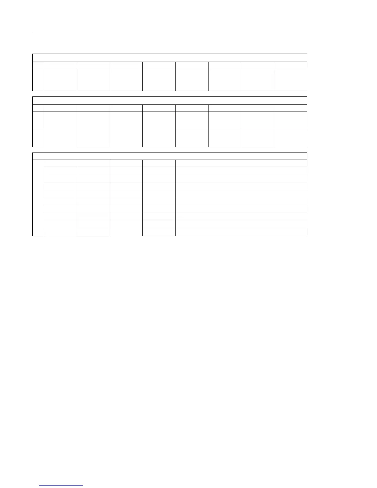
Motor status showed in the service program
From MCU (first data byte)
bit 7 bit 6 bit 5 bit 4 bit 3 bit 2 bit 1 bit 0
1 Indicate a
trip state with
no automatic
restart
Reset trip
state
Writing,
reading to
uP/EEPROM
Weight mode Unbalance
mode
Serial control
mode
Always 0 Always 0
From MCU (second data byte)
bit 7 bit 6 bit 5 bit 4 bit 3 bit 2 bit 1 bit 0
0 No short cir-
cuit
indication
DC-bus volt-
age OK
Interlock ON Motor
following
1 First short
circuit
indication
DC-bus volt-
age out of
range
Interlock
OFF
Motor is not
following
Error code
0 0 0 0 No error
0 0 0 1 1. High temperature FC
0 0 1 0 2. High temperature motor
0 0 1 1 3. Drive request but no interlock signal present
0 1 0 0 4. Communication error
0 1 0 1 5. Short-circuit
0 1 1 0 6. Error in interlock-circuits on FC
0 1 1 1 7. Under voltage on DC-bus
1 0 0 0 8. Over voltage on DC-bus
1 1 1 1 F. Motor not following
3.4 INTERNAL COM.
Not implemented.
3.5 EXTERNAL COM.
Activate the EXTERNAL COM. menu.
The display will now show the following submenu:
• RESTORE CBT
A password is needed to continue. The display will now show an eight figure code. Call authorized service and state
the code. Authorized service will assign a pass code. Enter the pass code you have been given and press the control
knob.
This will reset communication to factory default and the error code NO CBT COMMUNICATION will be reset.
3.6 DISPLAY TEST
Activate the DISPLAY TEST menu.
The display shows a grid for checking that all the segments in the display are intact. By turning the control knob, two
different grids and a completely white and a completely blank page are shown.
Press the control knob to exit.