18
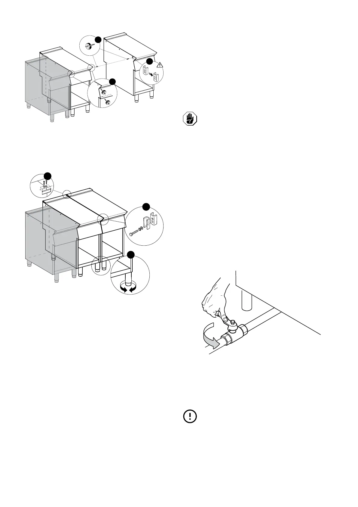
4. Turn one of the two plates inside the appliances 180℃
(Fig.1C);
5. From inside the control panel of the same appliance, join
them at the front side, screwing one M5x40 Hex Head
screw (supplied) on the opposite insert (Fig.1E);
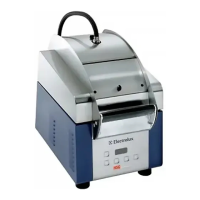
6. From the rear of the appliances, insert the coupling plate
(provided) in the side slots on the back panels;
7. Secure the plate with two flat head M5 screws provided
(Fig.1F).
F.4.1 Floor Fixing (depending on the appliance and/or
model)
To avoid accidental tipping of built-in half-module appliances
installed separately, fix them to the floor carefully following the
instructions enclosed with the corresponding accessory
(F206136).
F.4.2 Installation On Bridge, Cantilever Frame Or
Cement Plinth (depending on the appliance and/
or model)
Carefully follow the instructions enclosed with the correspond-
ing accessory. Follow the instructions supplied with the
optional product chosen.
F.4.3 Sealing Gaps Between Appliances
Follow the instructions supplied with the optional sealing paste
pack.
F.5 Floor fixing
To avoid accidental tipping of built-in half-module appliances
installed separately, fix them to the floor.
The instructions are enclosed with the corresponding acces-
sory (F206136).
F.6 Gas, electricity, water and other
connections (if present, depending on
the appliance and/or model)
• Any installation work or maintenance to the supply system
(gas, electricity, water and/or steam, if present) must only
be carried out by the utility company or an authorised
installation technician.
• Refer to the appliance dataplate for the product code.
• See the installation diagram for the type and position of
appliance connections.
F.7 Gas Connections
F.7.1 Introduction
CAUTION
This appliance is arranged and tested to
operate with G20 gas 20 mbar;
To convert it to another type of gas, follow the instructions in
F.7.6 Conversion to another type of gas paragraph of this
section.
F.7.2 Fume exhaust
• “A1“ type appliances have to be positioned under an
extraction hood to ensure removal of fumes and steam
produced by cooking;
(not relevant for Australian standard).
For AUSTRALIA: the ventilation must be in accordance with
Australian building codes and kitchen exhaust hoods must
comply with AS/NZS1668.1 and AS 1668.2.
F.7.3 Before connecting
1. Make sure the appliance is arranged for the type of gas to
be used.
Otherwise, carefully follow the instructions given in F.7.6
Conversion to another type of gas paragraph of this
section.
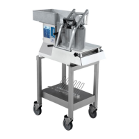
2. Fit a rapid gas shutoff tap/valve ahead of each appliance.
3. Install the tap/valve in an easily accessed place.
4. Clean the pipes to remove any dust, dirt or foreign matter
which could block the supply.
The gas supply line must ensure the gas flow necessary
for full operation of all the appliances connected to the
system.
A supply line with insufficient flow will affect correct
operation of the appliances connected to it.
IMPORTANT
Incorrect levelling of the appliance can affect
combustion and cause malfunctioning.
F.7.4 Connection (depending on the appliance and/or
model)
Monoblock models
1. See the installation diagram for the position of the gas
connection on the bottom of the appliance.
2. Remove the plastic cap protection (if present) from the
gas manifold before connecting.