19
Countertop models (Only for N9E range)
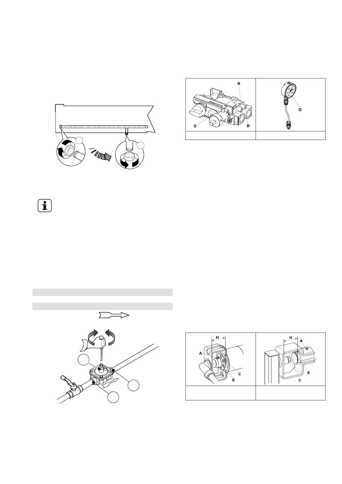
1. See the installation diagram for the position of the gas
connection on the bottom of the appliance.
2. Remove the plastic cap protection (if present) from the
gas manifold before connecting.
3. Countertop models can be connected to the gas supply
also using the rear connection:
a. operate at the back appliance;
b. unscrew the metal closing plug of the rear connection;
c. screw it tightly onto the bottom connection.
After installation, use soapy water to check connections for
leaks.
NOTE!
Only for Australia: The gas connection is male 1/
2 BSP.
F.7.5 Gas pressure regulator
The section of the gas supply line must be sufficient to ensure
the gas flow necessary for full operation of all the appliances
connected to the system.
If the gas pressure is higher than that specified or is difficult to
regulate (not stable), install a gas pressure regulator (acces-
sory code 927225) in an easily accessed position ahead of the
appliance.
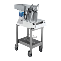
The pressure regulator should preferably be fitted horizontally,
to ensure the right outlet pressure.
1 connection side gas from mains
2 pressure regulator
3 connection side gas towards the appliance
The arrow on the regulator indicates the gas
flow direction.
For Australia: Adjust the test point pressure with burners
operating at maximum setting (see table “B“ of Appendix)
F.7.6 Conversion to another type of gas
Nozzle Table “B“ (see Appendix) gives the type of nozzles to
be used when replacing those installed by the manufacturer
(the number is engraved on the nozzle body).
At the end of the procedure, carry out the following check-list:
1. burner nozzle/s replacement
2. correct adjustment of primary air supply to burner/s
3. pilot nozzle/s replacement
4. minimum flame screw/s replacement
5. correct adjustment pilot/s if necessary
6. correct adjustment of supply pressure (see technical data/
gas nozzles table)
7. apply sticker (supplied) with data of new gas type used
F.8 Gas appliances regulations
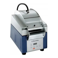
Valve – Fig. 1 Manometer – Fig. 2
F.8.1 Supply pressure checking (all versions)
1. Make sure the appliance is suitable for the type of gas
available, according to that given on the dataplate (other-
wise, follow the instructions given in F.7.6 Conversion to
another type of gas paragraph of this section).
The supply pressure must be measured while the appli-
ance operates, using a manometer (min. 0.1 mbar).
2. Remove the control panel;
3. Remove retaining screw “N“ from the pressure point (see
Valve – Fig. 1);
4. Connect the manometer “O“ (see Manometer – Fig. 2);
5. Compare the value read on the manometer with that given
in Table “B“ (see Appendix);
If the manometer gives a reading outside the range of
values in Table “B“, do not switch the appliance on;
Consult the gas company.
F.8.2 Gas valve outlet pressure adjustment
1. Remove the retaining screw from pressure point “B“ (see
Valve – Fig. 1);
2. Connect the manometer tube;
3. Supply the appliance with the correct nominal gas pres-
sure as given in F.8.1 Supply pressure checking (all
versions) paragraph.
4. Turn the fryer on;
5. Turn the outlet pressure adjustment screw of gas valve “D“,
clockwise to increase it and anticlockwise to reduce it
(consult the Appendix).
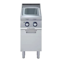
F.8.3 Primary air checking
Burner 15 L fryers / 23 L
fryers – Fig. 3
Burner 23 L tubes flame
fryers – Fig. 4
The primary air is correctly adjusted when the flame does not
float with the burner cold and there is no flareback with the
burner hot.
1. Undo screw “A“ (see Burner 15 L fryers / 23 L fryers – Fig.
3 or Burner 23 L tubes flame fryers – Fig. 4);
2. Position aerator “E“ at distance “H“ given in Table “B“ (see
Appendix);
3. Retighten screw “A“;
4. Seal with paint.