20
F.8.4 Main burner nozzle replacement
1. Loosen nut “A“ (see Burner 15 L fryers / 23 L fryers – Fig.
3 or Burner 23 L tubes flame fryers – Fig. 4);
2. Unscrew nozzle “C“ and the aerator “E“;
3. Replace nozzle “C“ with one suitable for the type of gas,
according to that given in table “B“ (see Appendix);
The nozzle diameter is given in hundredths of mm on the
nozzle body.
4. Insert nozzle “C“ into aerator “E“.
5. Fit the resulting assembly into its location.
6. Fully retighten nozzle “C“.
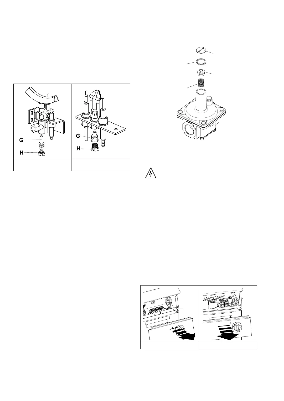
F.8.5 Replacing the pilot burner nozzle
Pilot 15 L fryers / 23 L tubes
flame fryers – Fig. 5
Pilot 23 L fryers – Fig. 6
1. Undo screw coupling “H“ (see Pilot 15 L fryers / 23 L tubes
flame fryers – Fig. 5 or Pilot 23 L fryers – Fig. 6);
2. Replace nozzle “G“ with one suitable for the type of gas
(see table “B“, Appendix);
The nozzle identification number is indicated on nozzle
body.
3. Retighten screw coupling “H“.
F.9 Before completing the installation
operations
• Use soapy water to check all gas connections for leaks.
• DO NOT use a open flame to check for gas leaks.
• Light all the burners separately and also together, to check
correct operation of the gas valves, rings and lighting.
• For each burner, adjust the flame regulator to the lowest
setting, individually and together.
• After completing the operations, the installer must instruct
the user on the correct method of use.
If the appliance does not work properly after carrying out all the
checks, contact the local Customer Care service centre.
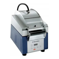
F.10 Replacing the adjustment spring of the
pressure regulator (Only for Australia)
To replace the spring “D“ of the pressure regulator with one
suitable for the gas pressure type indicated in table “B“ (see
Appendix) proceed as follows:
1. Remove the seal cap “A“, the seal cap gasket “B“, the
adjusting screw “C“ and the spring “D“ (see image);
2. Insert the new spring (blue colour = propane gas; silver
colour = natural gas) and replace the adjusting screw;
3. Connect a pressure gauge to the appliance’s test point
pressure – (see paragraph F.8.1 Supply pressure check-
ing (all versions));
4. Ignite the appliance’s burners so to have the maximum
gas consumption;
5. Regulate the adjustment screw until the pressure gauge
shows the working pressure value (see paragraph F.7.5
Gas pressure regulator);
6. Replace the seal cap and gasket and screw tightly closed;
7. Remove the pressure gauge and close the test point
pressure;
8. Prior to operation, test the gas pressure regulator for leaks.
F.11 Electrical connection
WARNING
Work on the electrical systems
must only be carried out by
specialised personnel.
Before connecting, make sure that:
1. the mains voltage and frequency match those indicated on
the appliance data plate;
2. there is an efficient earth contact;
3. the power supply is arranged and able to take the actual
current absorption and that it is correctly executed accord-
ing to the regulations and provisions in force in the country
of use.
4. a differential thermal-magnetic switch suitable for the input
specified on the dataplate, with contact gap enabling
complete disconnection in category III overvoltage con-
ditions and complying with the regulations in force, is
installed between the power cable and the electric line.
For the correct size of the switch, refer to the absorbed
current specified on the appliance dataplate.
F.11.1 Electrical appliances
15 L Fryers — Fig. 7 18 L Fryers — Fig. 8