Page 5
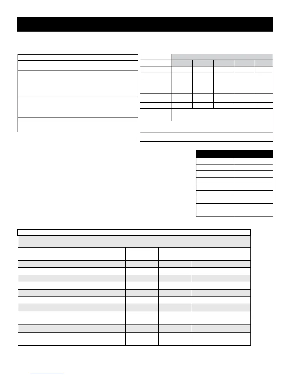
SURFACE TEMPERATURE LIMITS
1. Product must be undamaged, correctly assembled and have the cor-
rect oven temperature.
2. All skin temperatures are based on a room temperature of 77° F (25° C)
For ELECTRIC ranges built prior to 08/26/2003 - 400° F
For ELECTRIC ranges built after 08/26/2003 - 475° F
For GAS ranges built prior to 01/01/2004 - 400° F
For GAS ranges built after 01/01/2004 - 475° F
3. Oven must be cycling at designated test temperature for one hour
before test is conducted.
4. Pyrometers, (temperature testers), must be of high quality and properly
adjusted.
temperature of the range.
All gas and electric ranges must comply with U.L and A.N.S.I. surface temperature limits outlined in the following chart.
Note that the testing temperature is different for electric ranges produced after 08/26/2003.
MATERIAL TYPE / FINISH
PAINTED PORCELAIN GLASS
PLASTIC
†
METAL
LOCATION
Side Panel 152° F 160° F — — —
Oven Door 152° F 160° F 172° F 182° F —
Front Panel
152° F 160° F — — —
Knobs & Handles — — — *167° F
**182° F
131° F
**152° F
Skirt — — — *182° F *152° F
Cooktop
Oven Vent Area
NO TEMPERATURE LIMITS APPLY TO THIS AREA
†
Includes plastic with metal plating not more than 0.005” thick and metal with a plastic covering not
less than 0.005” thick.
* Self-Clean Gas Range at Clean Temperature
** Self-Clean Electric Range at Clean Temperature
RANGE TECHNICAL DATA
The chart seen here can be used to test the resistance of the oven
temperature sensor probe. For accuracy in testing use a high quality
thermometer or temperature meter to determine actual oven temperature
before reading the resistance of the probe.
RTD SCALE
TEMPERATURE °F RESISTANCE Ω
32 ± 1.9 1000 ± 4.0
75 ± 2.5 1091 ± 5.3
250 ± 4.4 1453 ± 8.9
350 ± 5.4 1654 ± 10.8
450 ± 6.9 1852 ± 13.5
550 ± 8.2 2047 ± 15.8
650 ± 13.6 2237 ± 18.5
900 ± 13.6 2697 ± 24.4
RTD TEMPERATURE / RESISTANCE CHART
MAXIMUM ALLOWABLE SURFACE TEMPERATURES
NOTE: RESISTANCE MEASUREMENTS ARE APPROXIMATE. VARIATIONS DUE TO TEMPERATURE CHANGES
AND OTHER FACTORS ARE NORMAL.
COMPONENT VOLTAGE
RATING
WATTAGE APPROXIMATE
BAKE ELEMENT
208 / 242 3000 16
BROIL ELEMENT 208 / 242 4000 14
WARMER DRAWER ELEMENT
108 / 132 700 20.5
WARMER DRAWER ELEMENT
108 / 132 450 32
MINI OVEN ELEMENT
108 / 132 1000 14
CONVECTION ELEMENT
108 / 132 350 40
CONVECTION ELEMENT
108 / 132 200 72
CONVECTION FAN MOTOR
WINDINGS
108 / 132 35
LOCK MOTOR WINDINGS
108 / 132 2000
OVEN TEMPERATURE SENSOR
PROBE (AT ROOM TEMPERATURE)
-
1100 *
*(refer to rtd chart)
Dual Fuel Range Component Resistance Chart