Page 29
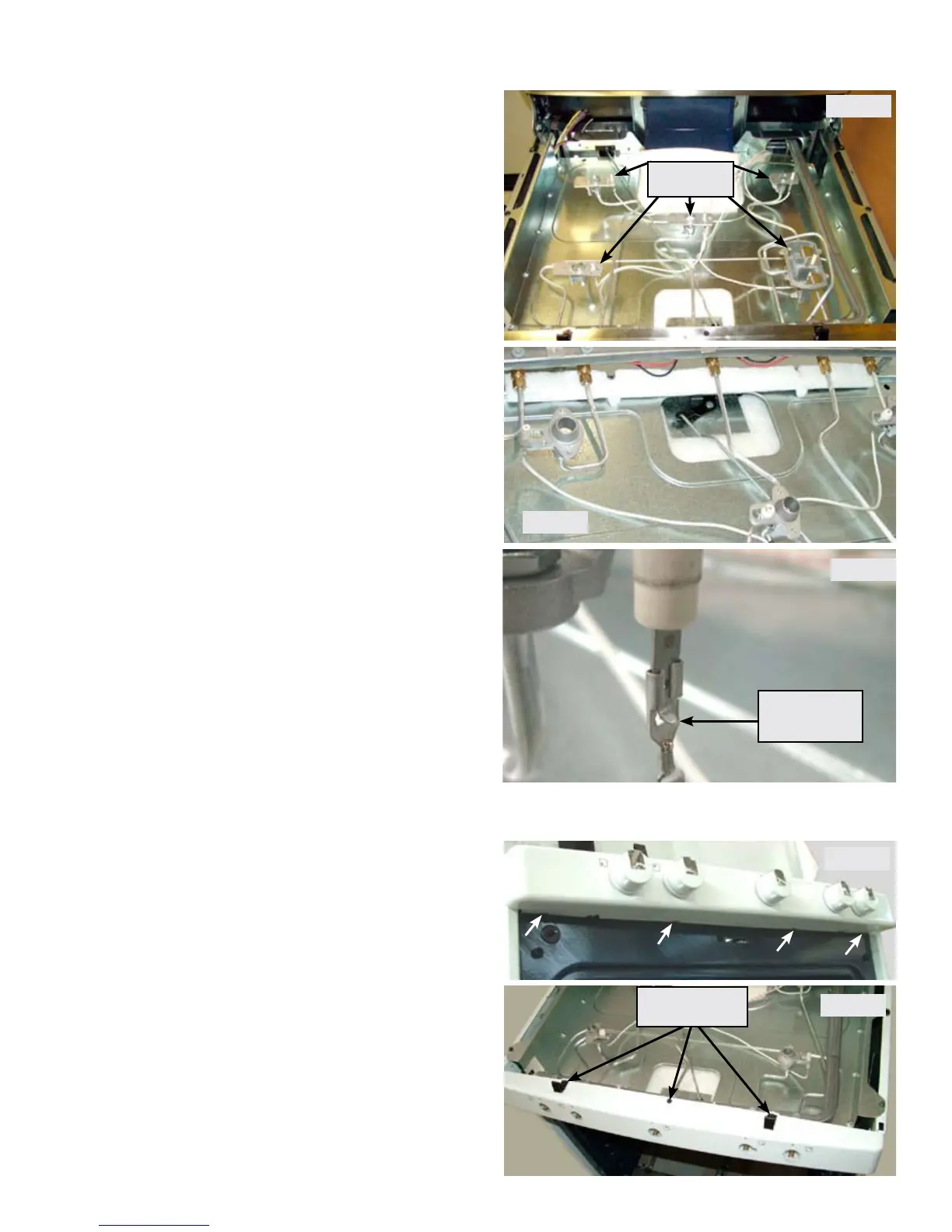
Once the cooktop has been removed the
individual orice holder assemblies are
accessible for service. (Photo A)
Each orice holder assembly is connected to
the burner valve by a compression tting on
the end of the gas supply line. (Photo B)
The supply line is part of the orice holder
assembly. Use care when removing and
installing the compression tting onto the
burner valve.
Photo B
When disconnecting the ignitor wire from
the ceramic ignitor on the orice holder you
must depress the locking tab in order for the
terminal connector to release.
Depress Tab
To Release
Photo C
Photo A
Orice Holder
Assemblies
Next remove the ¼” hex head screws securing
each of the main top mounting clips. Remove the
1/4” hex head screw in the center of the manifold
panel and remove the panel from the range.
(Photo E)
With the manifold panel removed the surface
burner ignitor switches and harness are
accessible. The wire harness and switches are
replaced as a complete assembly.
Removing Manifold Panel
Remove the four mounting screws indicated in
photo D on the underside of the manifold panel.
Remove the burner valve control knobs by pulling
them straight forward off the valve shafts.
Photo E
Remove Three
Screws
Photo D