22
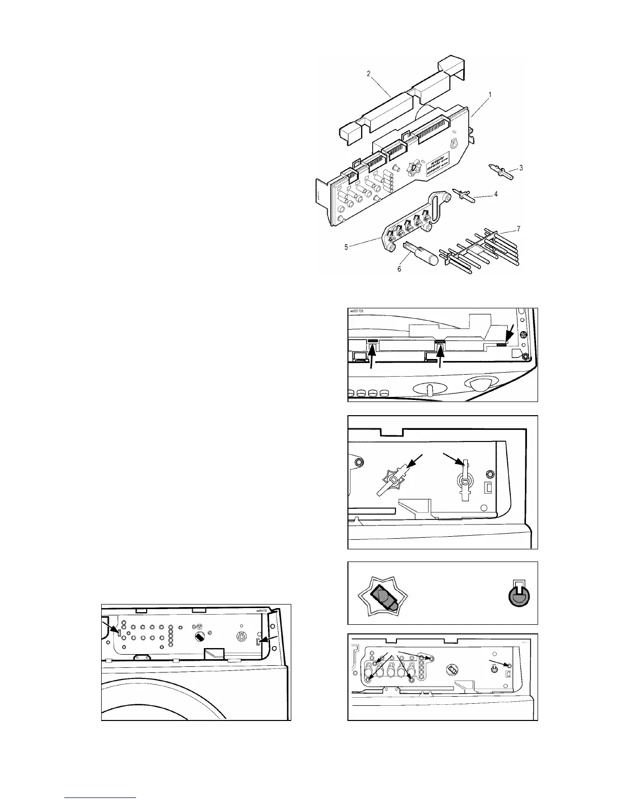
Electronic control board
1. PCB assembly + casing
2. Cover for connectors
3. Spindle of programme selector knob
4. Cover for connectors
5. Spindle of secondary selector knob
6. Pushbutton support panel
7. Pushbutton
8. LED diffuser
a. Remove the control panel.
b. Detach the cover for the connectors from the control
board casing.
c. Detach the wiring from the PCB.
d. If necessary, remove the coloured diffusers from the
board casing.
e. Remove the knob flanges from the spindles of the
selectors.
f. Remove the spindles from the selectors. Ensure that
the position of the selectors is as shown in the figure,
i.e. CANCEL/OFF for the programme selector, last
clockwise position for the secondary selector. Use
pliers to remove the spindle of the second selector (if
featured): this operation may damage the plastic
board casing; it is therefore advisable to use a new
spindle for the new board.
g. Remove the four screws which secure the
pushbutton support panel to the board and remove
the support/pushbutton assembly.
h. Remove the other screw which secures the board to
the control panel support.
i. Release the two anchor tabs and remove the
electronic board assembly.
b
e
f
g
h
i