E. E.
E. E.
E.
Carb Temp Probe Installation:Carb Temp Probe Installation:
Carb Temp Probe Installation:Carb Temp Probe Installation:
Carb Temp Probe Installation:
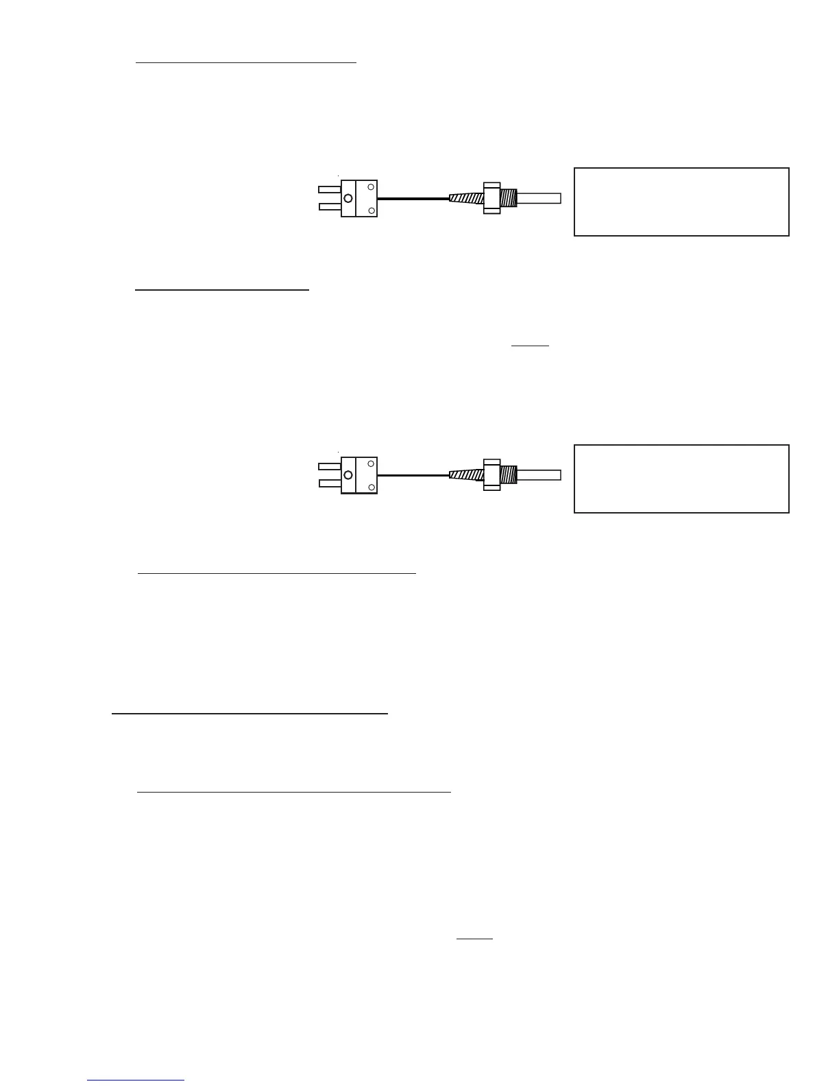
Remove the threaded plug located in the carburetor housing just below the throttle valve. Install the Carbu-
retor Temperature Probe (P-128) in this hole using a lock washer. Care should be taken not to over-tighten
the probe, thereby stripping the threads in the carburetor housing.
15
F. F.
F. F.
F.
OAT Probe Installation:OAT Probe Installation:
OAT Probe Installation:OAT Probe Installation:
OAT Probe Installation:
Mount the OAT Probe in an appropriate location on the aircraft, using the hardware supplied. The OAT
Probe is sensitive to air temperature changes. For this reason,
do not mount the OAT probe in the path of
the cowl or engine exiting air (i.e., on the belly of the aircraft). Also, if the probe is mounted in the cowling
area near a turbo or hot cylinder head, radiant heat may influence the probe temperature. Other than these
considerations, the OAT Probe may be mounted in an air intake vent, on the side of the cowling or anywhere
else on the aircraft.
P-128 Carb Temp / OAT Probe,
1/4" -28, Type K. Used on most
engines.
To EDC
Temp Input
(Middle Connector, Ch 8
Recommended)
P-128 Carb Temp / OAT Probe,
1/4" -28, Type K. Used on most
engines.
To EDC
Temp Input
(Middle Connector, Ch 8
Recommended)
G. G.
G. G.
G.
Other Temperature Probe Installation:Other Temperature Probe Installation:
Other Temperature Probe Installation:Other Temperature Probe Installation:
Other Temperature Probe Installation:
Other temperature probes (Cowl Temp, CDI Temp, Water Temp, etc.) may be installed using current
aircraft standards and practices (refer to AC 43.13). Make sure these probes do not interfere with the
operation of the engine or aircraft.
2.6 Install the Pressure Transducers:
Install only the Pressure Transducers applicable for your configuration.
A. A.
A. A.
A.
Manifold Pressure Transducer Installation:Manifold Pressure Transducer Installation:
Manifold Pressure Transducer Installation:Manifold Pressure Transducer Installation:
Manifold Pressure Transducer Installation:
Mount the PT-30ABS Pressure Transducer on the inside firewall or in the equipment bay under the aircraft
instrument panel. Use the holes in the bottom plate to mount the PT-30ABS. Only two mounting holes are
required.
An equipment bay can be made from a sheet of aluminum. Any piece of equipment or module used with the
MVP-50P can be mounted on the aluminum sheet using a Nut Plate or Riv-Nut to allow easy installation and
removal. The aluminum sheet is then mounted to the
inside firewall of the aircraft (using short spacers) and
should never have to be removed. Many aircraft are designed with an equipment bay.

 Loading...


