3.14 Connect the EDC Harness to Power and Ground:
Route the power wire (Top Connector, pin 37, Red Wire) to the MVP/EDC 5-amp Circuit Breaker. Route the
ground wire (Top Connector, pin 19, Black Wire) to the aircraft ground.
WARNING: The power wire is RED and is connected to pin 37 on the EDC Top Connector. If aircraft power is
connected to any pin on the EDC other than pin 37, damage to the EDC and any connected transducers may occur.
Insure power is provided on pin 37 of the EDC Top Connector before attaching the connector.
39
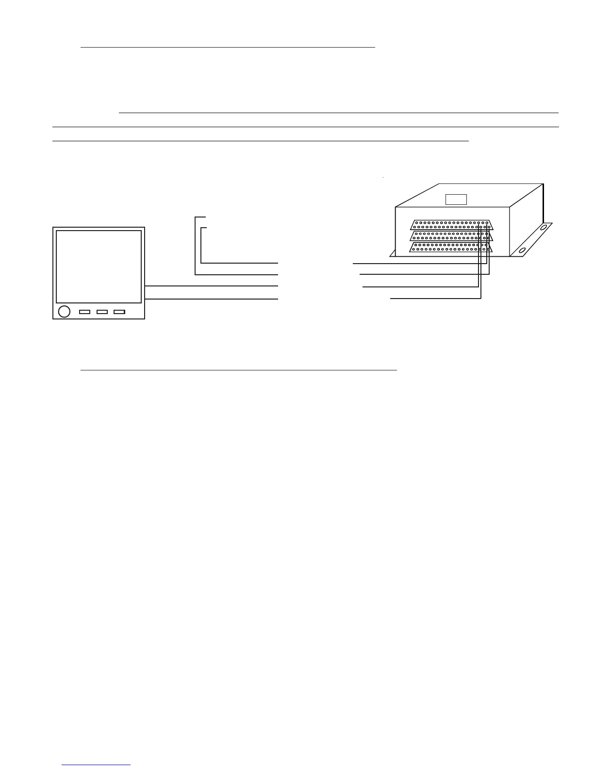
Top
MVP RS422-B (pin 12)
MVP RS422+A (pin 13)
Pin 37, Red Wire
Pin 19 Black Wire
Pin 36, White Wire
Pin 18, White/Green Wire
MVP
RS422 Input
To Aircraft Ground
To the MVP/EDC 5-amp Circuit Breaker
EDC-33P
3.15 Route the EDC RS422 Wires to the MVP Connector:
Route the RS422+A white/green wire and the RS422-B white wire to the MVP connector. These wires will be
connected to the MVP RS422 wires in a later step. If a second EDC is installed, see the Appendix for connec-
tion information.
When routing the MVP wire harness refer to the "MVP-50 25-pin D-Sub Connector Wiring Diagram" found at
the back of this manual. Insure no wires obstruct the freedom of travel of any controls.

 Loading...


