EDC Wiring Work Sheet
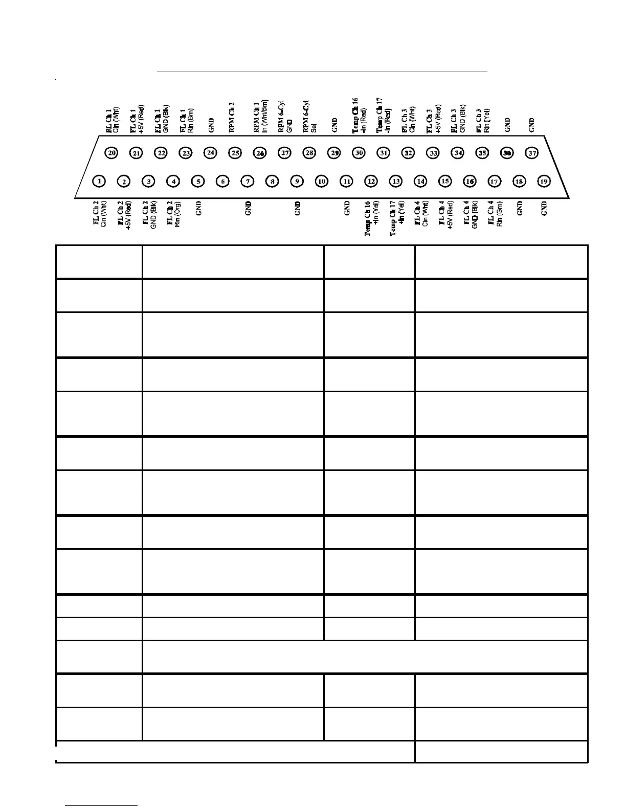
Bottom Connector (Back View, Wire Side)
EDC-33P-4/6EDC-33P-4/6
EDC-33P-4/6EDC-33P-4/6
EDC-33P-4/6
EDC Input EDC Pin #'s (Wire Colors) Function
Probe, Module or
Direct Connection to the EDC
FL Ch 1
(Resistive Input)
Rin Pin 23 (Brn)
(Requires a RFLM-4 Module)
FL Ch 1
(Capacitive Input)
Cin Pin 20 (Wht)
+5V Pin 21 (Red)
Gnd Pin 22 (Blk)
FL Ch 2
(Resistive Input)
Rin Pin 4 (Org)
(Requires a RFLM-4 Module)
FL Ch 2
(Capacitive Input)
Cin Pin 1 (Wht)
+5V Pin 2 (Red)
Gnd Pin 3 (Blk)
FL Ch 3
(Resistive Input)
Rin Pin 35 (Yel)
(Requires a RFLM-4 Module)
FL Ch 3
(Capacitive Input)
Cin Pin 32 (Wht)
+5V Pin 33 (Red)
Gnd Pin 34 (Blk)
FL Ch 4
(Resistive Input)
Rin Pin 17 (Grn)
(Requires a RFLM-4 Module)
FL Ch 4
(Capacitive Input)
Cin Pin 14 (Wht)
+5V Pin 15 (Red)
Gnd Pin 16 (Blk)
RPM Ch 1 In Pin 26 (Wht/Brn)
LEFT (mag) RPM-Pickup
RPM Ch 2 In Pin 25 (Wht/Orange)
RIGHT (mag) RPM-Pickup
RP M 6- C yl Select Ground pin 28 to pin 27 to se le ct 6-cyl
operation (open for 4-cyl operation)
N/A N/A
Temp Ch 16 +In Pin 12 (Yel)
-In Pin 30 (Red)
Temp Ch 17 +In Pin 13 (Yel)
-In Pin 31 (Red)
Note: Any EDC Input not used should be marked "N/A" under Function. 0425051-4
MVP-50P-4/6MVP-50P-4/6
MVP-50P-4/6MVP-50P-4/6
MVP-50P-4/6
Open for 4 Cly Engines.
Short Pin 28 to 27 for 6 Cyl Eng.
Ring Terminal Isolator
Ring Terminal Isolator
Note: Resistive Fuel Level Inputs may also be used to measure Digital signals.
+5V
+5V
+5V
In (White/Org)

 Loading...


