37
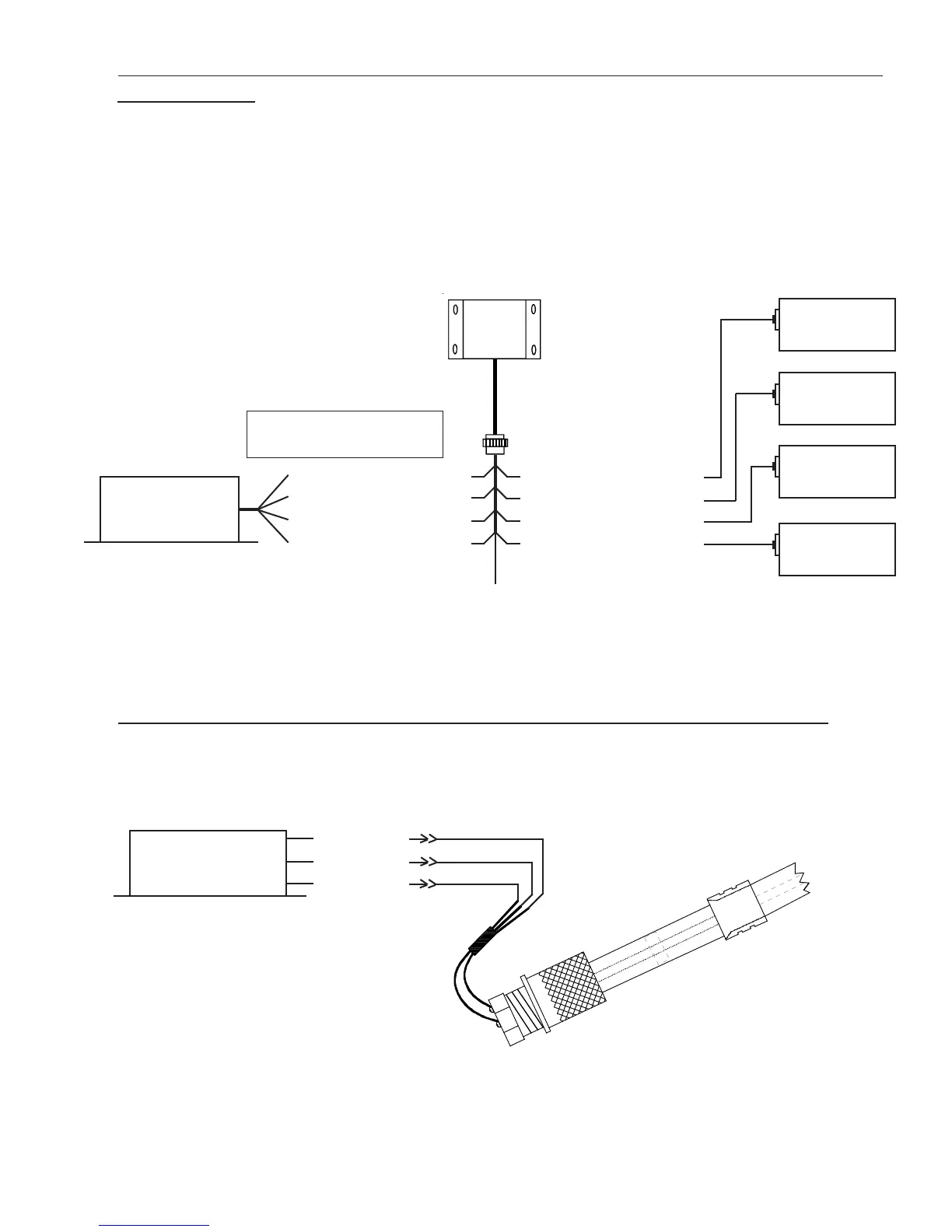
3.7 Connect the RFLM-4-x Harness to the EDC Connector and to the Resistive Fuel
Level Sensors:
DO NOT connect the RFLM into a capacitive system, damage may occur. Route the appropriate resistive fuel
level input wires (for the number of tanks to be monitored) in the RFLM-4-x harness to the EDC Bottom
Connector. Plug the wires into the appropriate resistive fuel level channels. The excessive wire can be cut and
spliced, bundled and tie wrapped up or cut to length and new D-Sub pin installed (see the “Working with
Connectors” section of this manual for more information). Route and connect the corresponding wires in the
RFLM-4-x wire harness to the appropriate fuel tank sensors. Route the red wire (in pin 1 of the RFLM-4-x
connector) to the aircraft bus via the MVP/EDC 5-amp circuit breaker.
Ch 1 Rin, Pin 2 (Brown)
Ch 2 Rin, Pin 3 (Orange)
Ch 3 Rin, Pin 4 (Yellow)
Ch 4 Rin, Pin 5 (Green)
Ch 1 Rin, Pin 6 (Brown)
Ch 2 Rin, Pin 7 (Orange)
Ch 3 Rin, Pin 8 (Yellow)
Ch 4 Rin, Pin 9 (Green)
EDC
Resistive Input
(1 of 4)
+Vin, Pin 1, (Red)
To Bus (via MVP/EDC Circuit Breaker)
Fuel Tank
1
Fuel Tank
2
Fuel Tank
3
Fuel Tank
4
RFLM-4-12V (for a 12Volt system)
RFLM-4-24V (for a 24Volt system)
Bottom Connector
Connect only the wires for
which you have Fuel Tanks.
3.8 Connect the EDC Harness to the EI P-300C Capacitive Fuel Level Probes:
Route the appropriate capacitive fuel level wires (for the number of tanks to be monitored) in the EDC har-
nesses to the capacitive fuel level probes. Cut the wires to length, install the appropriate connectors (see the
“Working with Connectors” section of this manual for more information) and connect to the capacitive fuel
level probe.
+5V (Red)
Gnd (Black)
Cin (White)
P-300C Capacitive
Fuel Level Probe
EDC
Capacitive Input
(1 of 4)
Bottom Connector
Note: The capacitive fuel level channels are shared with the resistive channels. A single capacitive
and resistive channel cannot be used simultaneously.

 Loading...


