11
Chapter 7
INSTALLATION MANUAL |
7 ATTENTION POINTS FLUE GAS EXTRACTION
To guarantee the re safety regarding you ue gas conguration a casing
is necessary. For this case non-combustible materials should be used.
Make sure to ventilate a shaft and never to insulate it, to make sure the
hot air is able to get away.
Every transit or terminal should be made such, that the warmth-
insulation and non-combustability is guaranteed, according to the
building regulation.
7�1 DETERMINING THE FLUE GAS EXTRACTION DIAMETER
The Sky series replaces have a ue diamter of 200/130. The maximal
vertical length is 22m. There is no minimal start length for these
replaces, which means that you can start with a bend directly on the
replace.
Calculating the Total Vertical Section (TVS)
You calculate the Total Vertical Section by adding up all vertical upward
sections in the extraction gradation.
Calculating the Total Horizontal Section (THS)
You calculate the Total Horizontal Section by adding up all horizontal
parts in the extraction gradation.
7�1�1 REFERENCE THE FLUE CALCULATION
In order to ascertain whether your intended extraction shall function
properly, a stove category is determined.
After you have determined the applicable category i.e. a wall or a roof
terminal (see APPENDIX EAPPENDIX E), you search for the corresponding calculation
tables.
Each category refers to a set of tables:
1. A table for horizontal outlet.
2. A table for vertical outlet
You must use the table applicable to you. You calculate your total
vertical section (TVS) as well as your total horizontal section (THS). In
the table you will nd advice; TVS on the vertical axis and THS on the
horizontal axis.
7�2 BENDS
Be aware of the bends in your ue. They provide extra resistance in the
system and must therefore be included in the TVS and THS.
There are 2 bend types as per the example in Figure 8.2:
• Type N bends: 45° and 90° bends from vertical to horizontal and
vice versa.
• Type Q bends: 45° and 90° bends from horizontal to horizontal.
The rst 3 type N bends (from vertical to horizontal) do not need to be
included in your calculations. The next type N bends are each calculated
as 1 horizontal meter in the THS.
For a type Q bend (horizontal to horizontal) the following applies:
• 90° bend in the horizontal section counts as 2 horizontal meters
in the THS.
• 45° bend in the horizontal section counts as 1 horizontal meter in
the THS
Extraction sections in a 45° upward pipe:
• 45° upward sections are calculated both vertically and horizontally.
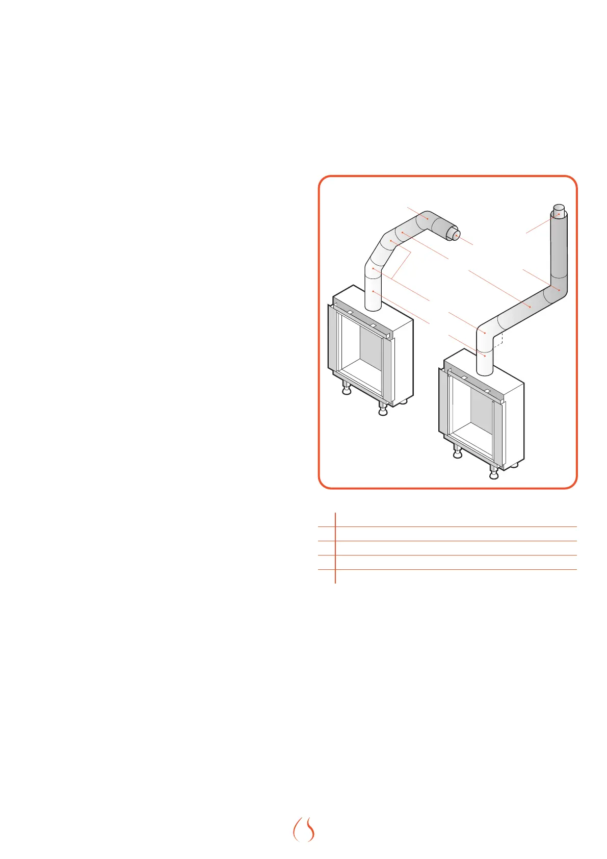
Q
R
T
N
S
N
R
Figure 7.6 | Flue bends examples
R Horizontal or vertical terminal
N Bend 45° & 90° vertical to horizontal and vice versa
Q Bend 45° & 90° horizontal to horizontal
T Pipe section horizontal
S Pipe section vertical
Table 7.1 |