12
Chapter 7
INSTALLATION MANUAL |
7�2�1 CALCULATE FLUE LENGTH
Not all parts can be adjusted! To t the drainage system correctly, you
are to use an adjustable tting. You can use an adjustable concentric
pipe, wall or roof tting. To get a sealed ue gasconnection, the inner
pipe must always be 2 cm longer than the outer pipe. Always attach
adjustable parts with a chuck parker.
For proper operation of the replace it is important that the ue pipe
meets the requirements. To determine this, we prepared a chart. (See
APPENDIX EAPPENDIX E)
The following outcomes can be found for each intersection of TVS and
THS;
Result Action
V
No ristrictor required
O
Position the resitrictor
X
No good operation guaranteed *
A
O
means you have to put in a restrictor plate in your replace. The
restrictor is supplied with the replace.
7�3 POWER-FAN
For ue congurations that do not function on natural draft, the PowerFan
can be used. For extensive installation instructions and the operation of
the PowerFan we refer to the manual of the PowerFan on the Element4
website or via your dealer.
7�4 INSTALLATION OF FLUE MATERIAL
Follow the following instrucions for the installation of ue materials;
• Drill a hole of 160 mm for the wall or roof transit with a 150 mm
diameter ue connection, and 210 mm with a ue with a diameter
of 200 m.
• In a situtation of non-combustible materials keep a distance of at
least 50 mm between the outside of the concentric pipes and the
wall or ceiling.
• Provide a (re) safe transit construction in wall, oor or roof
sheeting. Whenever venting passes through a wall, an approved
heat shield or ‘wall thimble’ must be installed.
• Build up the system from the replace.
• Assemble pipes in the correct direction! The inner pipe goes into
and the outer pipe goes over the replace connection.
• Make sure the tubes are suciently braced, so the weight of the
tubes are not supported on the replace.
• The concentric pipes could come loose due to expansion and
cooling down. It is recommended that a chuck parker be used in
places that are inaccessible after installation.
• The horizontal ue sections must be tted sloping to the replace.
• In case of long horizontal stretches, it is advised to install a tap
point into the ue, at its lowest point, to be able to drain the
condensation formed during burning of gas.
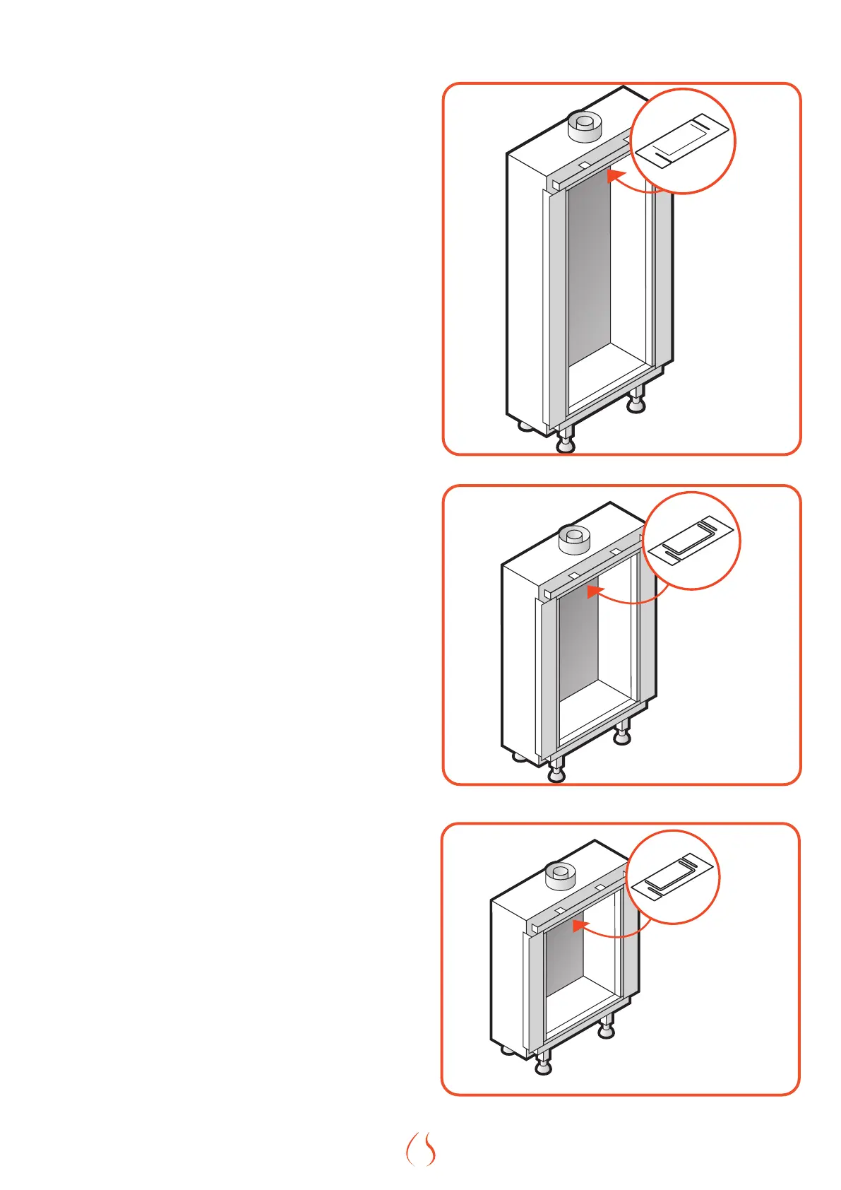
Figure 7.1 | Position Flue Restrictor Sky L
Figure 7.2 | Position Flue Restrictor Sky M
Figure 7.3 | Position Flue Restrictor Sky S