17
Chapter 9
INSTALLATION MANUAL |
9�2 SERVICING THE BURNER
A fault nding chart is included in APPENDIX AAPPENDIX A for the Mertik control
system tted to this appliance. Access the Burner via the maintenance
access.
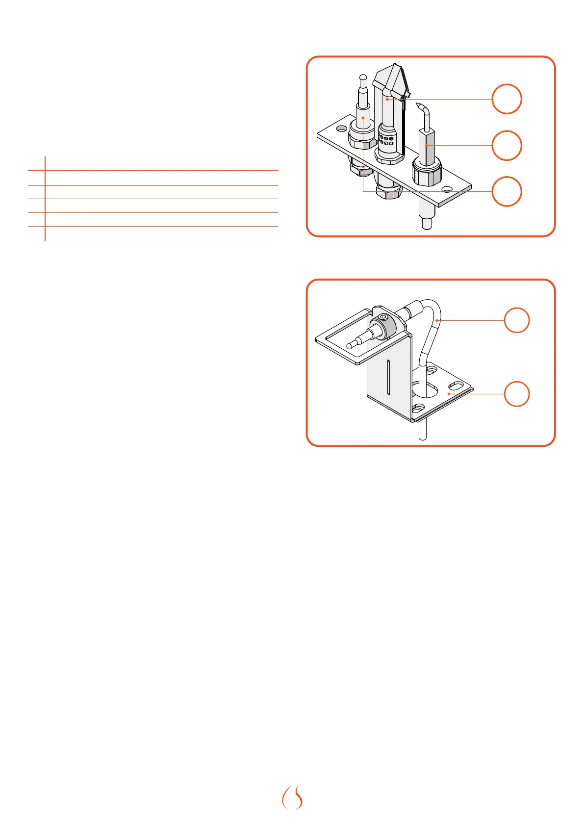
For the maintenance of the burner dierent parts can be distinguished,
all mentioned below. See Figure 9.2 |and Figure 9.3 | and Table 9.2 |for
more info.
# Part
1 Pilot ame
2 Ignitor Rod
3 Pilot Thermocouple
4 Second Thermocouple
5 Thermocouple stand
Table 9.2 |
9�2�1 BURNERS
The ames from the burners should be visually checked. The ame
should have a small blue base and be bright yellow. Too orange ames
indicate too little oxygen. Flames that are too blue have too much
oxygen. The oxygen in the primary air can be adjusted slightly at the
venturi throttles, but should not be necessary.
Maintenance of the burner should also be unnecessary. If this is the case,
check the burner pressure at the inlet to the burner. The instructions of
changing the burner pressure and the correct pressure per gastype can
be found in
9�2�2 PILOT
The pilot ame must be visually checked. The pilot ame must always be
present when the appliance is in operation and should appear as shown
in Figure 9.2 |.
The pilot has two distinct ames, one engulng the thermocouple on its
left, the other reaching across to the burner.
The area around the pilot should be inspected for cleanliness. Lint or
foreign material must be removed with a brush or vacuum.
9�2�3 THERMOCOUPLES
The Element4 replaces have two thermocouples; one next to the pilot
and one opposite the pilot side of the burner. The completeness and
operation of both must be checked. A qualied installer must conrm
that both thermocouples are in place and undamaged. While checking
the thermocouple, please ensure that the ignitor rod is not cracked as
well.
1
2
3
Figure 9.10 | Isometric drawing of the pilot set
Figure 9.11 | Isometric drawing of second thermocouple