EasyManuals Logo

Elite CSW-200-UL Series User Manual

Elite CSW-200-UL Series
40 pages
To Next Page IconTo Next Page
To Previous Page IconTo Previous Page
Page #21 background imageLoading...
Page #21 background image
20
S
t
r
i
k
e
O
p
e
n
P
u
s
h
B
u
t
t
o
n
S
t
r
i
k
e
O
p
e
n
P
u
s
h
B
u
t
t
o
n
2
4
V
o
l
t
s
D
C
2
4
V
o
l
t
s
D
C
F
i
r
e
D
e
p
t
K
e
y
S
w
i
t
c
h
F
i
r
e
D
e
p
t
K
e
y
S
w
i
t
c
h
M
/
S
L
i
n
k
M
/
S
L
i
n
k
C
l
a
s
s
2
S
u
p
p
l
y
C
l
a
s
s
2
S
u
p
p
l
y
C
e
n
t
e
r
L
o
o
p
C
e
n
t
e
r
L
o
o
p
S
a
f
e
t
y
L
o
o
p
S
a
f
e
t
y
L
o
o
p
R
a
d
i
o
R
e
c
e
i
v
e
r
R
a
d
i
o
R
e
c
e
i
v
e
r
E
x
i
t
L
o
o
p
E
x
i
t
L
o
o
p
GG
BB AA
++
O
m
n
i
C
o
n
t
r
o
l
S
u
r
g
e
S
u
p
p
r
e
s
s
o
r
P
/
N
Q
4
1
0
P
a
t
e
n
t
P
e
n
d
in
g
P
/
N
Q
4
1
0
P
a
t
e
n
t
P
e
n
d
in
g
®
CENTER SAFETY EXIT
CENTER SAFETY EXIT
FIRE
DEPT.
13
STRIKE
OPEN
RADIO
RECEIVER
TIMER
SYSTEM ON
EXIT
LOOP
ALARM
SENSOR
REVERSE
SENSOR
OPEN
STOPCLOSE
SAFETY
LOOP
CENTER
LOOP
GATE
LOCKED
60
POWER
OVERLOAD
OFF
W4
OPEN LEFT
DC-BACKUP
ALARMSENSOR
OPEN RIGHT
3
SENSORS
RESET
MOTOR
13
13
COMMAND
PROCESSED
ON
GB
MS LINK
A
MADE IN USA
S
t
r
i
k
e
O
p
e
n
P
u
s
h
B
u
t
t
o
n
S
t
r
i
k
e
O
p
e
n
P
u
s
h
B
u
t
t
o
n
2
4
V
o
l
t
s
D
C
2
4
V
o
l
t
s
D
C
F
i
r
e
D
e
p
t
K
e
y
S
w
i
t
c
h
F
i
r
e
D
e
p
t
K
e
y
S
w
i
t
c
h
M
/
S
L
i
n
k
M
/
S
L
i
n
k
C
l
a
s
s
2
S
u
p
p
l
y
C
l
a
s
s
2
S
u
p
p
l
y
C
e
n
t
e
r
L
o
o
p
C
e
n
t
e
r
L
o
o
p
S
a
f
e
t
y
L
o
o
p
S
a
f
e
t
y
L
o
o
p
R
a
d
i
o
R
e
c
e
i
v
e
r
R
a
d
i
o
R
e
c
e
i
v
e
r
E
x
i
t
L
o
o
p
E
x
i
t
L
o
o
p
GG
BB AA
++
O
m
n
iC
o
n
t
r
o
l
S
u
r
g
e
S
u
p
p
r
e
s
s
o
r
P
/
N
Q
4
1
0
P
a
t
e
n
t
P
e
n
d
in
g
P
/
N
Q
4
1
0
P
a
t
e
n
t
P
e
n
d
in
g
®
CENTER SAFETY EXIT
CENTER SAFETY EXIT
FIRE
DEPT.
13
STRIKE
OPEN
RADIO
RECEIVER
TIMER
SYSTEM ON
EXIT
LOOP
ALARM
SENSOR
REVERSE
SENSOR
OPEN
STOPCLOSE
SAFETY
LOOP
CENTER
LOOP
GATE
LOCKED
60
POWER
OVER LOAD
OFF
W4
OPEN LEFT
DC-BACKUP
ALARMSENSOR
OPEN RIGHT
3
SENSORS
RESET
MOTOR
13
13
COMMAND
PROCESSED
ON
GB
MS LINK
A
MADE IN USA
TIMER
TIMER
NSOR
60
OFF
OFF
OPEN LEFT OPEN RIGHT
3
13
ON
TIMER
TIMER
NSOR
60
OFF
OFF
OPEN LEFT OPEN RIGHT
3
13
ON
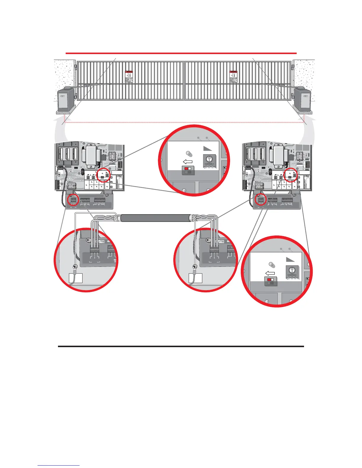
Master Omni Board Slave Omni Board
1. Connect G from the master surge suppressor to G of the slave surge suppressor.
2. Connect B from the master surge suppressor to B of the slave surge suppressor.
3. Connect A from the master surge suppressor to A of the slave surge suppressor.
4. Turn timers on BOTH Omni boards to the “OFF” position
CHASSIS
GROUND
M
/
S
L
i
n
k
M
/
S
L
i
n
k
P
/N
Q
4
10
P
ate
n
t
P
en
d
in
g
P
/N
Q
4
10
P
ate
n
t
P
en
d
in
g
Center
Loop
Center
Loop
GG BB
AA
CHASSIS
GROUND
M
/
S
L
i
n
k
M
/
S
L
i
n
k
P
/N
Q
4
1
0
Paten
t
Pen
d
in
g
P
/N
Q
4
1
0
Paten
t
Pen
d
in
g
Center
Loop
Center
Loop
GG BB
AA
Use Shielded Twisted Wires
to Connect the Surge
Suppressor of each
Gate Operator Together
Use low voltage wires in separate conduit to connect gate operators together
Caution: Never run high voltage and low voltage wires in same conduit
MASTER AND SLAVE WITH TIMER OFF
PARTIAL MASTER/INDIVIDUAL CONTROL
IN ORDER FOR THE FOLLOWING OPERATION TO OCCUR, FOLLOW THE INSTRUCTIONS.
EXAMPLE: There is a double gate, the entry gate is to be opened with a radio transmitter and the exit gate
with a free exit loop. Only one safety loop system is to open both gates, and a fire department switch should
open both gates at the same time.
1. Connect the radio receiver to entry gate only.
2. Connect the exit loop to exit gate only.
3. Connect the safety loop to both entry and exit gates. (Observe polarity of voltage)
4. Connect the fire department switch to both entry and exit gates. (Observe polarity of both operators)

Questions and Answers:

Question and Answer IconNeed help?

Do you have a question about the Elite CSW-200-UL Series and is the answer not in the manual?

Elite CSW-200-UL Series Specifications

General IconGeneral
BrandElite
ModelCSW-200-UL Series
CategoryGate Opener
LanguageEnglish

Related product manuals