S
t
r
i
k
e
O
p
e
n
P
u
s
h
B
u
t
t
o
n
S
t
r
i
k
e
O
p
e
n
P
u
s
h
B
u
t
t
o
n
2
4
V
o
l
t
s
D
C
2
4
V
o
l
t
s
D
C
F
i
r
e
D
e
p
t
K
e
y
Sw
i
t
c
h
F
i
r
e
D
e
p
t
K
e
y
Sw
i
t
c
h
M
/
S
L
i
n
k
M
/
S
L
i
n
k
C
l
a
s
s
2
S
u
p
p
l
y
C
l
a
s
s
2
S
u
p
p
l
y
C
e
n
t
e
r
L
o
o
p
C
e
n
t
e
r
L
o
o
p
S
a
f
e
t
y
L
o
o
p
S
a
f
e
t
y
L
o
o
p
R
a
d
i
o
R
e
c
e
iv
e
r
R
a
d
i
o
R
e
c
e
iv
e
r
E
x
i
t
L
o
o
p
E
x
i
t
L
o
o
p
GG
BB
AA
––
++
O
m
n
i
C
o
n
t
r
o
l
S
u
r
g
e
S
u
p
p
r
e
s
s
o
r
P/N Q410
P
atent P
ending
P/N Q410
P
atent P
ending
®
5
(NO2)
4
(NC2)
3
(NC1)
2
(NO1)
1
(C1)
6
(C1)
42 to 240VAC
24 to 240VDC
LIGHT ON
DARK ON
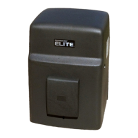
OMRON Retro-Reflective Photocell Wiring
Surge Terminal Wiring for Electronic Box
Wiring for
OmniControl
Board
CENTER SAFETY EXIT
CENTER SAFETY EXIT
FIRE
DEPT.
13
STRIKE
OPEN
RADIO
RECEIVER
TIMER
SYSTEM ON
EXIT
LOOP
ALARM
SENSOR
REVERSE
SENSOR
OPEN
STOPCLOSE
SAFETY
LOOP
CENTER
LOOP
GATE
LOCKED
60
POWER
OVER LOAD
OFF
W4
OPEN LEFT
DC-BACKUP
ALARMSENSOR
OPEN RIGHT
3
SENSORS
RESET
MOTOR
13
13
COMMAND
PROCESSED
ON
GB
MS LINK
A
MADE IN USA
P
ALARMSENSOR
Important:
This switch must
be in the “Light
On” position for
the system to
function properly
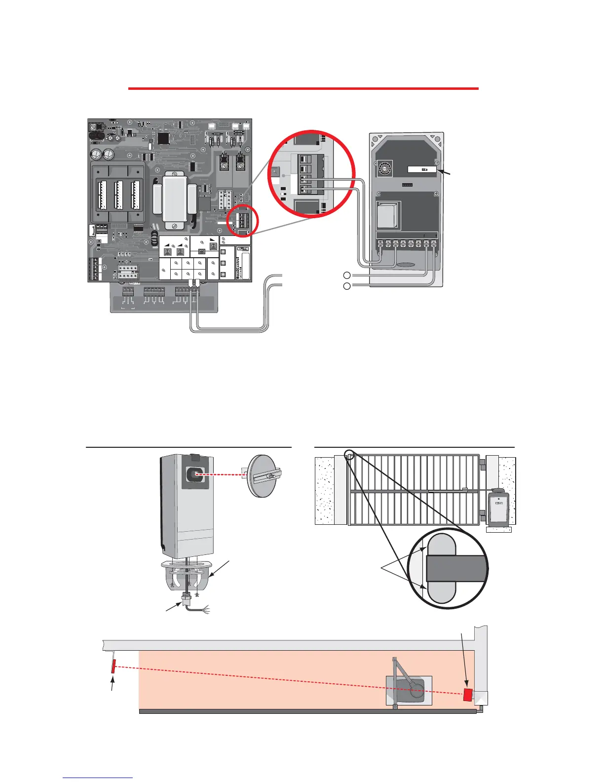
If you are going to use a non-contact sensor as a secondary entrapment protection you
should use a recognized component to comply with the revised UL 325 intended to be used
in class I or class II gate operator, like the following: OMRON Retro-Reflective Photocell,
Model: E3K-R10K4-NR
If multiple sensors are being used, all of the photo
beam sensors are to be connected in parallel at the
sensor input on the Omni Control board.
ELITE Part #
A OMRON
Radio Receiver +
Radio Receiver
-
 Loading...