10
Installation Guide Flatpack2 -48V 150A ~ 2029242 R2, May 2008
4. Electrical Installation
CAUTION: V
ERIFY THAT ALL
AC
CIRCUIT BREAKERS FEEDING THE SYSTEM ARE IN THE
OFF
POSITION
.
K
EEP ALL
AC
BREAKERS OFF UNTIL ALL APPROPRIATE SYSTEM CONNECTIONS
HAVE BEEN MADE AND VERIFIED
.
R
EFER TO SECTION
9
FOR STARTUP CHECKLISTS
.
WARNING:
F
OR SAFETY REASONS
(
HIGH LEAKAGE CURRENT AND HIGH TOUCH CURRENT
)
ALWAYS CONNECT THE
AC
EARTH WIRE
(PE)
TO THE TERMINALS BEFORE CONNECTING
AC
INPUT CABLE
(
S
).
Flatpack2 rectifiers have an input voltage range of 85 to 300 VAC (Nominal 185 –
275 VAC), with a frequency range between 45 and 66Hz. See the User’s Guide—
Flatpack2 Rectifier Modules (350002.013) for further details.
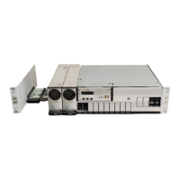
The AC junction box of each rectifier shelf contains a
knockout hole for a standard trade-size conduit with a
diameter of 0.75”.
To wire the AC input terminal block:
1) Remove the cover located at the
rear of each rectifier shelf using a
Phillips screwdriver (two screws).
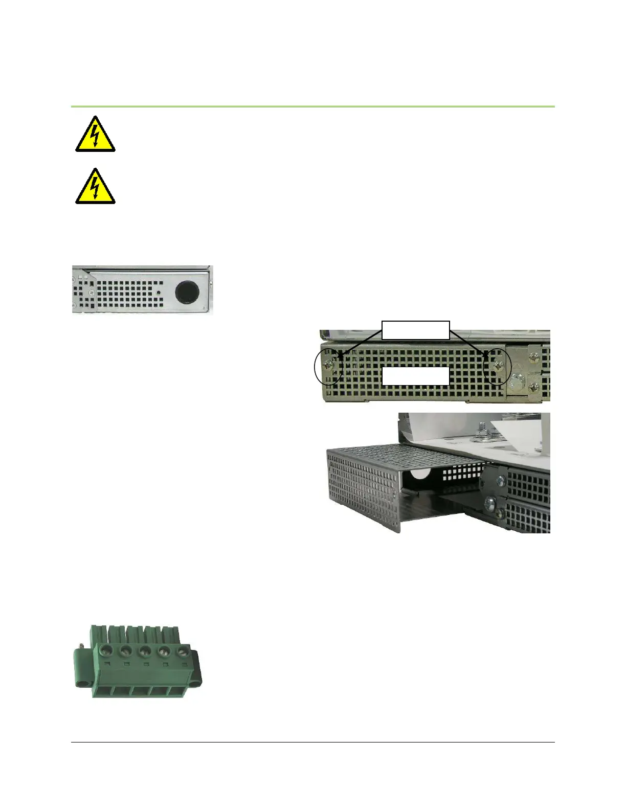
2) Unscrew and remove the green AC
connector using a Phillips or flat
blade screwdriver.
3) Use a small flat blade screwdriver to
open each terminal and install AC
wiring. See the sections “Individual
Feed” on page 11 and “Dual Feed” on
page 11 for wiring details.
4) Pull a green safety wire in the AC
mains conduit and terminate it to
the ground terminal of the
connector. It should be longer in length than the black and white AC wires.
5) Double-check that each connection is secure and replace the connector.
6) If necessary, terminate additional safety wires to the
shelf ground termination stud located to the right of
the connector (see Figure 4 and Figure 5).
7) Replace the cover after AC terminations are
complete. Make sure to line up the bottom plate
between the guides on the bottom of the shelf.
Figure 3 - AC Terminal
Block (Removed)
Figure 2 - AC Input Cover
 Loading...