List of figures and tables
Page 9
List of figures and tables
Figure 1 The AIS network .................................................................. 17
Figure 2 What’s in the box? ............................................................... 19
Figure 3 Typical AIS transceiver connection...................................... 21
Figure 4 Mounting the AIS transceiver............................................... 23
Figure 5 Desk mounting the AIS transceiver ..................................... 24
Figure 6 Panel mounting the AIS transceiver .................................... 25
Figure 7 GNSS Antenna location....................................................... 26
Figure 8 GNSS Antenna connection.................................................. 27
Figure 9 VHF Antenna location.......................................................... 28
Figure 10 VHF Antenna connection..................................................... 29
Figure 11 Serial input port connection ................................................. 30
Figure 12 14 Way connector cable wiring connections........................ 31
Table 1 14 Way connector serial data ports ..................................... 31
Figure 13 Serial bi-directional port connection..................................... 32
Figure 14 18 Way connector cable wiring connections........................ 33
Table 2 18 Way connector serial data ports ..................................... 33
Table 3 Alarm relay connections ...................................................... 34
Figure 15 Power connection ................................................................ 35
Table 4 Power supply connections ................................................... 35
Figure 16 Grounding the AIS transceiver............................................. 36
Figure 17 Enter password screen ........................................................ 39
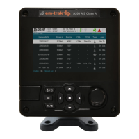
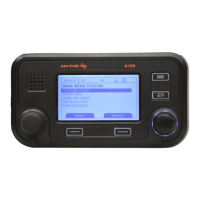
Figure 18 AIS Transceiver front panel ................................................. 41
Figure 19 Home page menu screen .................................................... 43
Figure 20 Main menu structure ............................................................ 44
Figure 21 Display layout ...................................................................... 45
Table 5 Status indicators .................................................................. 47
Table 6 Alarms list ............................................................................ 50
Figure 22 Vessel dimension measurement.......................................... 54
Figure 23 Target list screen ................................................................. 57
Figure 24 AIS target symbols displayed .............................................. 58
Figure 25 Micro SD card Socket .......................................................... 60
Figure 26 Convoy dimensions screen.................................................. 64
Figure 27 Blue Sign interface connection options................................ 66
Figure 28 Input port schematic ............................................................ 67