Copy right © 2018 Shenzhen Emakefun Technology co., Ltd.
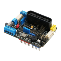
Table 1 WS2812 chip pin function table
Figure 9-1 Schematic diagram of the pin function of the WS2812 chip
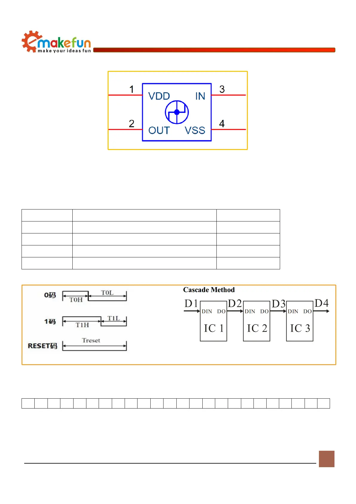
WS2812 RGB LED Light Driving principle
The WS2812 RGB LED low level is represented by T0, which is 0.5μs high level 2μs low level. T1
consists of a low level of 2μs and a low level of 0.5μs. Low level time above 50μs during reset.
0 yards, high voltage time
1 yard, high voltage time
0 yards, low voltage time
Reset code, low voltage time
时序波形图如下
Figure 9-2 Waveform timing diagram and connection method
24bit data structure
Drive RGB LED light
There are two RGB LED lights RGB1 and RGB2 on the PS2X&Motor Driver Board. You can control the
RGB light-off timing by programming. You can also set the color of the RGB light (example program file