detection and shaping, and is directly supplied to the single chip microcomputer, and the corresponding
operation is performed to achieve the purpose of controlling the motor.
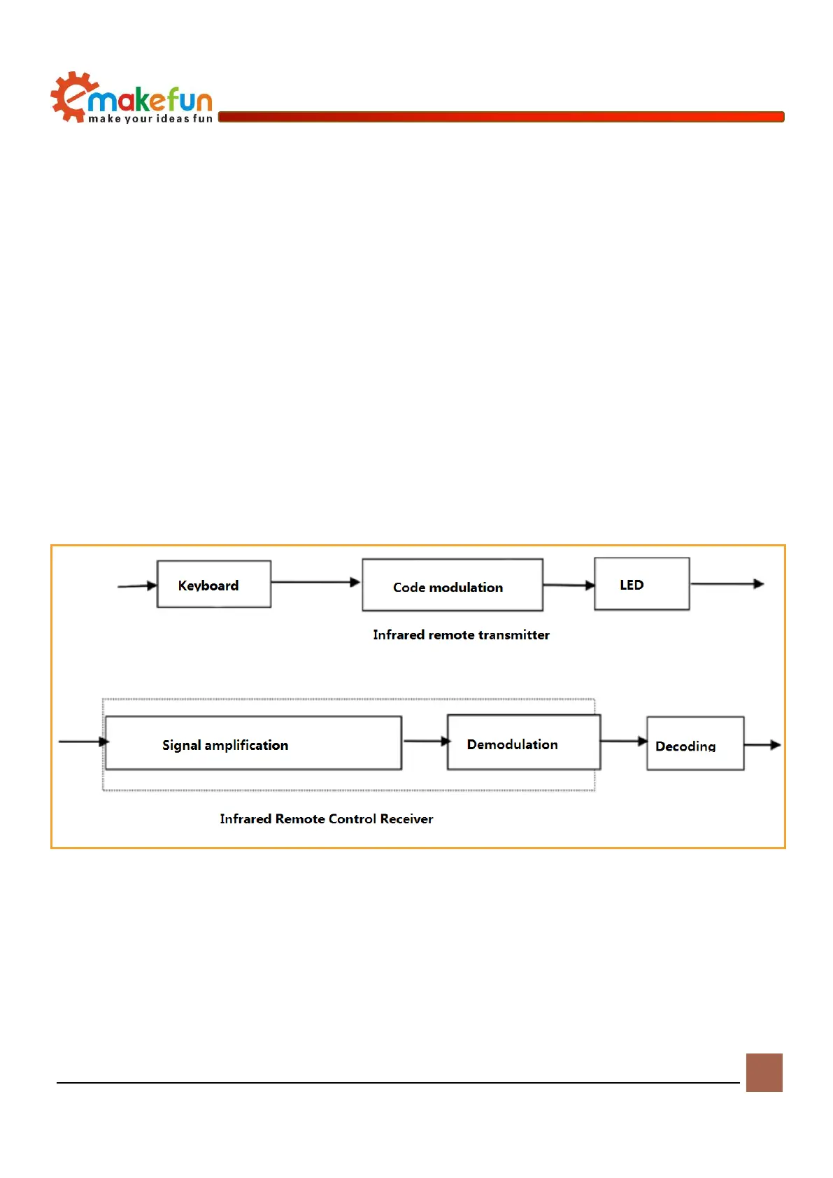
Working Principle
The remote control system generally consists of a remote control (transmitter) and a receiver. When
you press any button on the remote control, the remote control generates a corresponding code pulse to
output various infrared-based control pulse signals. The pulse is a computer command code. The infrared
monitor diode monitors the infrared signal and then sends the signal to the amplifier and the limiter. The
limiter controls the pulse amplitude to a certain level regardless of the distance between the infrared
transmitter and the receiver. The AC signal enters the bandpass filter. The bandpass filter can pass the load
wave of 30KHZ to 60KHZ, enter the comparator through the demodulation circuit and the integration
circuit, and the comparator outputs high and low levels to restore the signal waveform of the transmitter. As
shown in the 13-2 system fram diagram.
Figure 13-2 Block diagram of the infrared transmitting and receiving system
Driving infrared remote control
There is an infrared remote control receiving probe on the PS2X&Motor Driver Board (as shown in
Figure 14-1). (Example program file path: Load file -> ArduinoDemo -> IrkeyPressed -> IrkeyPressed.ino)
After burning the sample program, turn on the power. Switch, and open the serial monitor, use the remote
control to press the different buttons on the infrared receiver on the driver board, you will see different