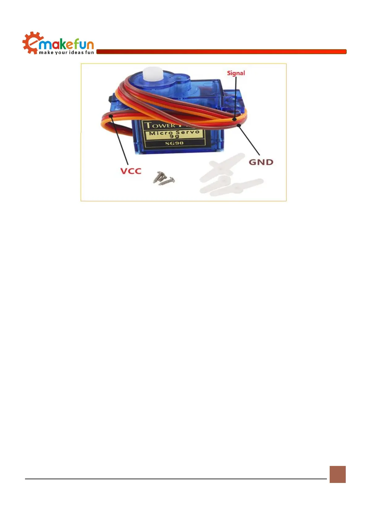
Figure 11-2 Physical diagram of the servo
Working principle of servo
The servo control signal enters the signal modulation chip from the channel of the receiver to obtain a
DC bias voltage. It has a reference circuit inside, which generates a reference signal with a period of 20ms
and a width of 1.5ms, and compares the obtained DC bias voltage with the voltage of the potentiometer to
obtain a voltage difference output. Finally, the positive and negative voltage output of the voltage difference
to the motor drive chip determines the forward and reverse of the motor. When the motor speed is constant,
the potentiometer is rotated by the cascade reduction gear, so that the voltage difference is 0, and the motor
stops rotating.
When the control circuit board receives the control signal from the signal line, the motor is controlled to
rotate, the motor drives a series of gear sets, and after deceleration, the drive is transmitted to the output
steering wheel. The output shaft of the steering gear and the position feedback potentiometer are connected.
When the steering wheel rotates, the position feedback potentiometer is driven. The potentiometer will
output a voltage signal to the control circuit board for feedback, and then the control circuit board
determines the motor according to the position. The direction and speed of rotation to achieve the target
stop. The workflow is: control signal → control circuit board → motor rotation → gear set deceleration →
steering wheel rotation → position feedback potentiometer → control circuit board feedback.