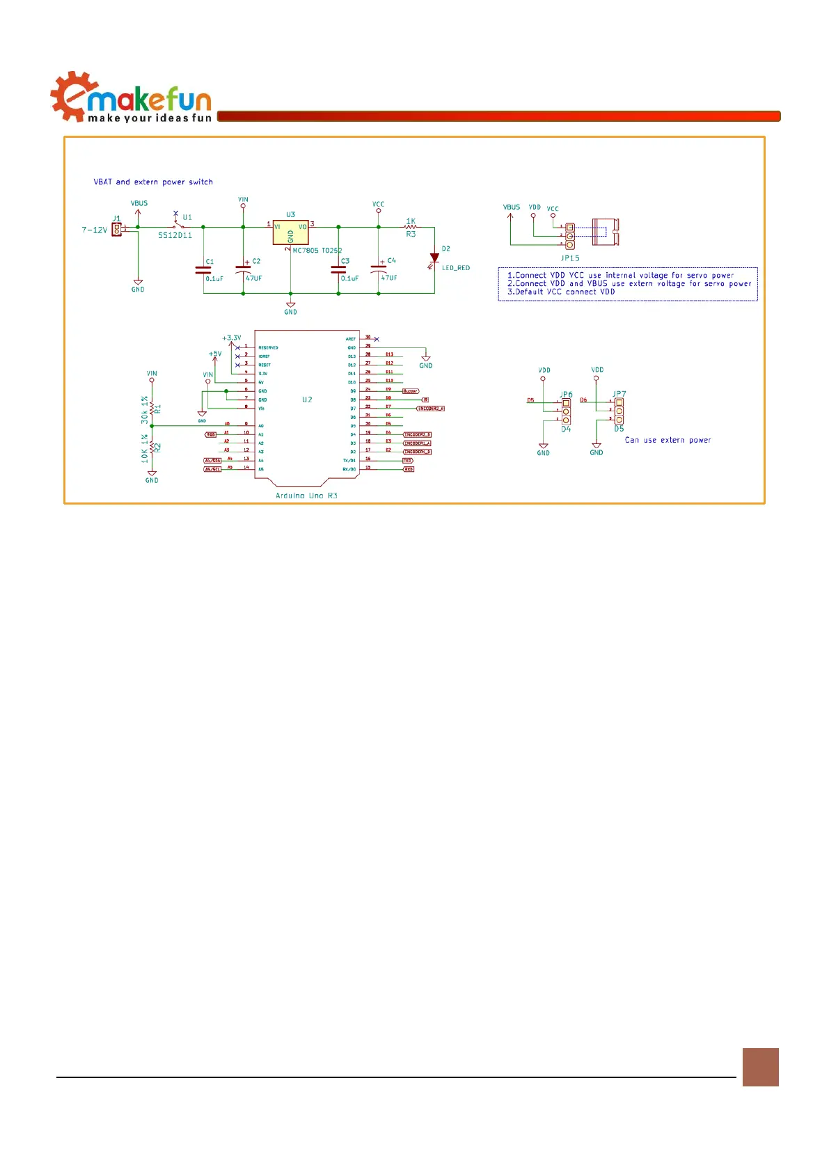
Figure 5-1 Power schematic
DC Motor
Motor control principle
The PS2X&Motor Driver Board uses the PCA9685 to output the PWM control motor driver chip
TB6612FNG. Now we’ll briefly introduce the two chips.
The main parameters of PCA9685 are as follows:
◆ I2C interface control can control 16-channel PWM and support up to 16 servos or PWM output, 12-bit
resolution for per channel (4096 levels)
◆ Built-in 25MHz crystal oscillator, can be connected to external crystal oscillator or can also not be
connected to external crystal oscillator, up to 50MHz.
◆ Supporting 2.3V-5.5V voltage, maximum withstand voltage is 5.5V
With power-on reset, software reset and other functions
The device address of the PCA9685 is determined by the pins A0, A1, A2, A3, A4, and A5, and the pin
cannot be left floating. Since there are six pins that together determine the device address, there are 64
device addresses. Since the IC keeps the LED All Call address (E0h, 1110 000) and Software Reset address
(06h, 0000 0110) after power-on, there are only 62 available device addresses. Therefore, theoretically one
I2C interface can control the way 16* 62=992 PWM, the pin control device address is shown in the figure