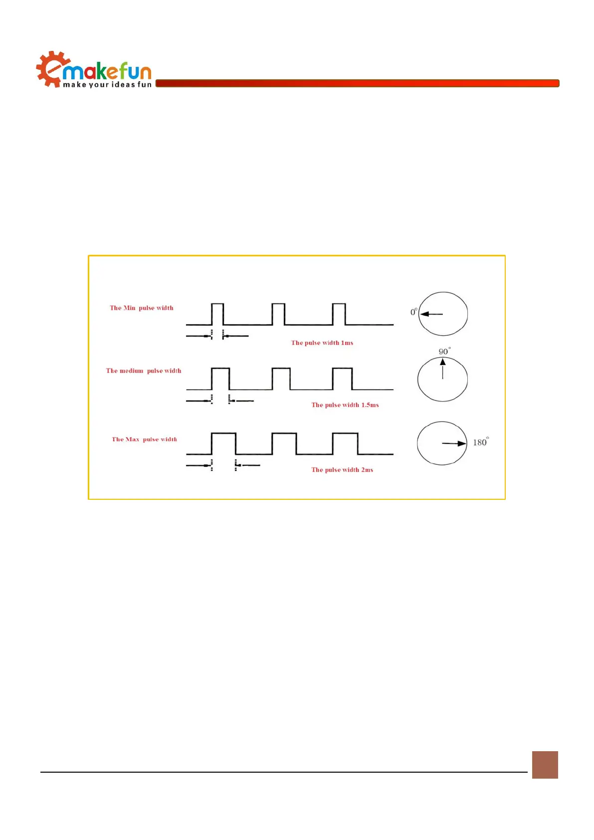
The control signal period of the servo is 20MS pulse width modulation (PWM) signal, the pulse width is
from 0.5-2.5MS, and the corresponding steering wheel position is 0-180 degrees, which varies linearly. That
is to say, give him a certain pulse width, its output shaft will maintain a certain corresponding angle, no
matter how the external torque changes, until it is given a pulse signal of another width, it will change the
output angle to the new corresponding position is shown in Figure 11-3. There is a reference circuit inside
the steering gear to generate a reference signal with a period of 20MS and a width of 1.5MS. There is a
comparator that compares the applied signal with the reference signal to determine the direction and size to
produce the motor's rotation signal.
Figure 11-3 Relationship between servo output angle and input pulse
Drive Servo
The PS2X&Motor Driver Board driver board can drive the servo, the servo pin position on the driver
board (red pin), with ground pin (GND), power pin (VCC) and signal pin (S), three the pins are respectively
connected to the corresponding pins of the servo (Fig. 11-4). The servos can also be controlled by I2C
communication, as shown in Figure 11-5. (Example program file path: Load file -> ArduinoDemo -> Servo
-> I2C_Servo.ino) After burning the sample program, connect the serial port and observe the data printed by
the serial port; or program the steering gear to rotate in different directions. We can realize the steering of
the robot by driving the rotation of the steering gear, or the sensor probe Installed on the steering gear to
adjust the detection direction of the sensor through the servo. The schematic diagram of the servo interface
is shown in Figure 11-6.