CHAPTER 3. INSTALLATION 26
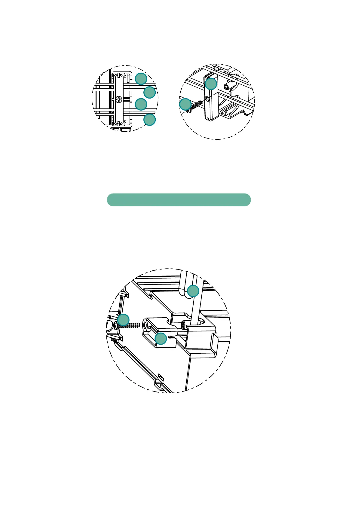
6
5
4
3
2
1
Figure 3.11: Cord relief assembly
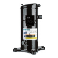
The compressor motor cable assembly is through the inverter enclosure and must
follow the sequence shown in Figure 3.12.
Motor Cable Routing Description
Indicator Description
1 Compressor Cable
2 Cord Relief
3 Fixing Screw
3
2
1
Figure 3.12: Compressor cable cord relief