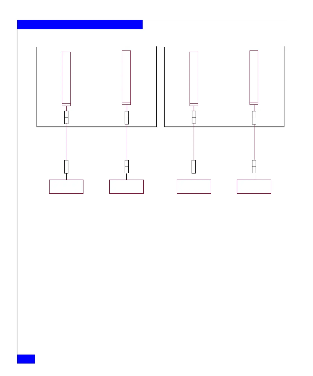
Zone B
AC input
cable B
Cable connectors are shown as
they exit the bottom rear of the
DMX bays.
This cabling is internal
to the DMX bays.
The customer’s AC power feeds
are connected to these two
three-phase connectors.
DMX storage bay
rear view
Zone A
AC input
cable A
Zone B PDP
(left)
Zone A PDP
(right)
15 ft.
Extension cord
15 ft.
Extension cord
Customer’s power
distribution unit
number B
Customer’s power
distribution unit
number A
Zone B
AC input
cable B
Cable connectors are shown as
they exit the bottom rear of the
DMX bays.
This cabling is internal
to the DMX bays.
The customer’s AC power feeds
are connected to these two
three-phase connectors.
DMX system bay
rear view
Zone A
AC input
cable A
Zone B PDP
(left)
Zone A PDP
(right)
15 ft.
Extension cord
15 ft.
Extension cord
Customer’s power
distribution unit
number B
Customer’s power
distribution unit
number A

 Loading...


