108 EMC VNX8000 Hardware Information Guide
Disk-array enclosures
Disk drive layout
Looking at the 3U, 120 DAE from the front and above (Figure 90), the inside of each DAE
has physically printed labels located on the left and right sides of the DAE enclosure.
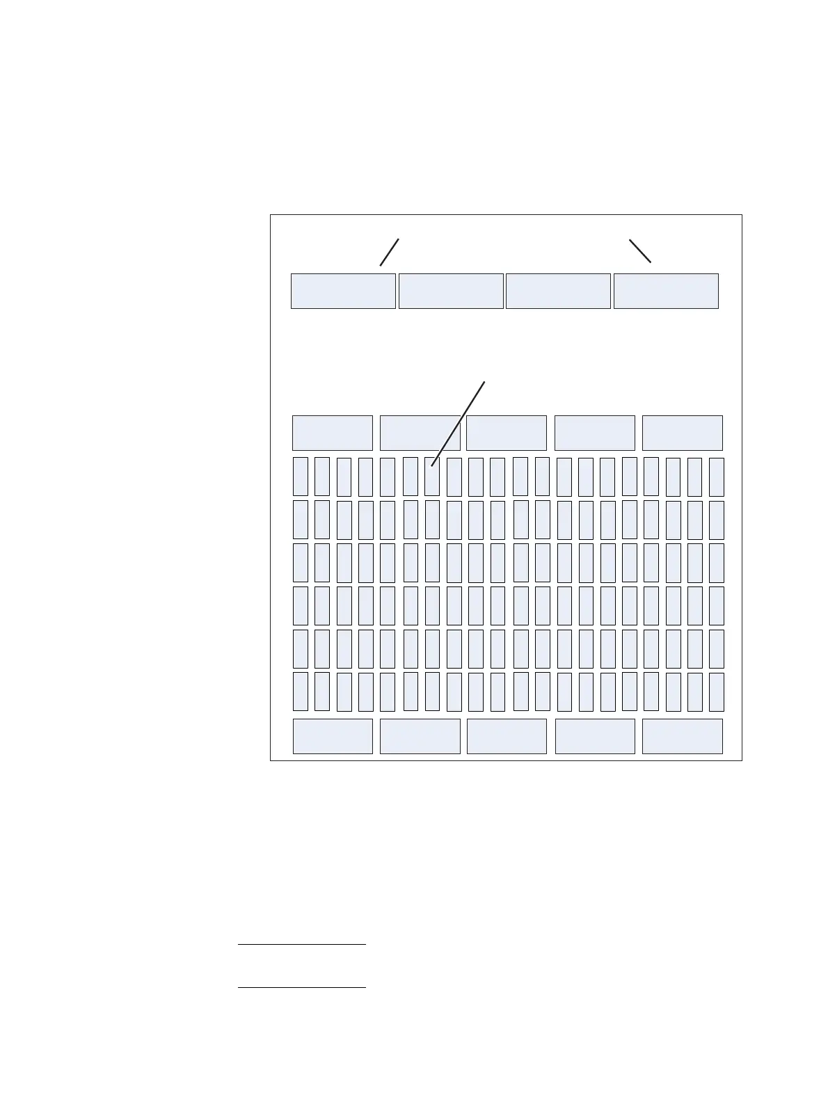
Figure 90 3U, 120 DAE disk drive layout and notation (top-down interior view)
These labels describe the rows (or banks) and the columns (or slots) of where the disks
are installed in the DAE. From front to back, the DAE is labeled on the left A0, B0, C0, D0,
E0, and F0 while on the right, the DAE is labeled A19, B19, C19, D19, E19, and F19. The
letters in front of the numbers denote the row (or bank) while the numbers denote the
column (or slot).
Note: The labels for the banks and slots shown in Figure 90 are the actual labels in the 3U,
120 DAE.
A
0
B
0
C
0
D
0
E
0
Rear of 3U DAE
Front of 3U DAE
Fan module Fan module Fan module Fan module Fan module
F
0
A
19
B
19
C
19
D
19
E
19
F
19
Fan module Fan module Fan module Fan module Fan module
Power supply module Power supply module Power supply module Power supply module
Link control card Link control card
Disk drive

 Loading...


