Disk-array enclosures
EMC VNX8000 Hardware Information Guide 127
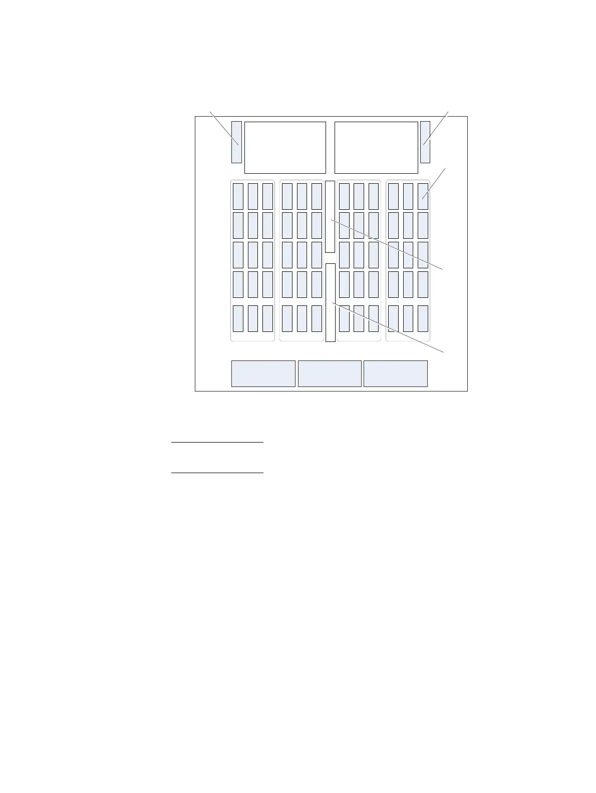
Figure 109 4U, 60 (2.5- or 3.5-inch) DAE disk drive layout and notation (top-down interior view)
Note: The labels for the banks, slots, and LCCA shown in Figure 109 are the physical labels
in the 4U, 60 (2.5- or 3.5-inch) DAE.
Fan control module (cooling module)
Each 4U, 60 (2.5- or 3.5-inch) DAE includes three fan control modules (cooling modules)
located on the front of the DAE. The fan control module includes a fan, fuse, and
microcontroller with an I
2
C interface inside a rugged enclosure.
The fan control module augments the cooling capacity of each 4U, 60 (2.5- or 3.5-inch)
DAE. It plugs directly into the DAE baseboard from the top of the DAE. Inside the fan
control module, sensors measure the external ambient temperatures to ensure even
cooling throughout the DAE.
A
B
C
D
E
Rear of 4U DAE
Front of 4U DAE
VNX-000650
0 1 2 3 4 5 LCCA 6 7 8 9 10 11
Cooling Module Cooling Module Cooling Module
Power Supply Module Power Supply Module
Inter Connect Module (ICM) Inter Connect Module (ICM)
Disk drive
LCC B
LCC A

 Loading...


