126 EMC VNX8000 Hardware Information Guide
Disk-array enclosures
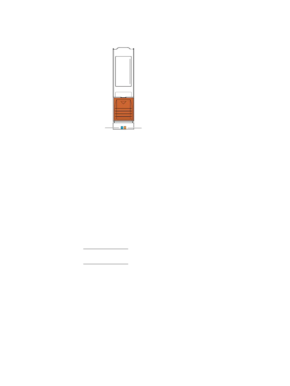
Figure 108 shows an example of the disk drive power and fault LEDs.
Figure 108 Disk drive power LED and fault LED
Disk drive layout
Looking at the 4U, 60 (2.5- or 3.5-inch) DAE from the front and above (Figure 109), the
inside of each DAE has physically printed labels located on the left and the front sides of
the DAE. These labels describe the rows (or banks) and the columns (or slots) of where
the disks are installed in the DAE. The banks are labeled from A to E, while the slots are
labeled from 0 to 11.
Rules for disk drive population
The required order of loading the disk drives into a 4U DAE is (Figure 109):
1. Start at row (or bank) A, slot 0.
2. Fill up row (or bank) A before inserting any disk drives into row B.
3. Continue this order until you fill all the rows with row E being the last row filled.
Note: If a partially filled row is available, the remaining empty slots are to be loaded with
filler panel modules.
Disk drive
fault LED
(amber)
Disk drive
power LED
(blue)

 Loading...


