166 EMC VNX8000 Hardware Information Guide
Eight- and sixteen-bus DAE cabling
As described in Table 58 on page 165, the resulting numbering scheme for the upgraded
VNX8000 is shown in Figure 133 on page 166 and Figure 134 on page 167. These figures
show the 6-Gb/s SAS IO module slot location, the port location in the I/O module, and the
cable labels from the I/o module side to the LCC side on the respective DAE.
◆ “Slot 4 (sixteen-bus) upgraded configuration” on page 166
◆ “Slot 6 (sixteen-bus) upgraded configuration” on page 167
Slot 4 (sixteen-bus) upgraded configuration
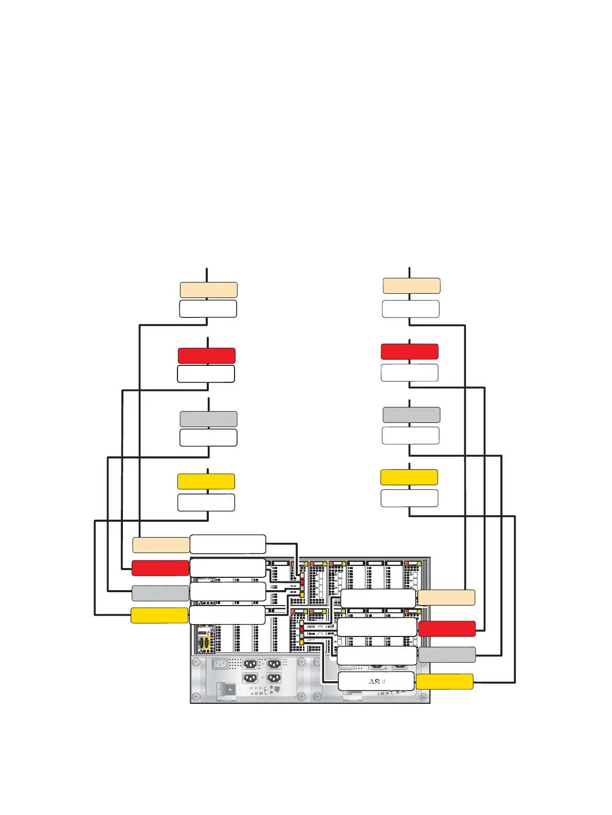
The following figure shows the location of the 6-Gb/s SAS I/O module slot (slot 4), the I/O
module port location (0, 1, 2, and 3), and the cable labels for both the I/O module side
and the corresponding LCC side in the DAE it connects to (Figure 133). For more
information, refer to Table 57 on page 162.
Figure 133 Example continuation of a sixteen-bus upgrade configuration of a VNX8000 with the
6-Gb/s SAS I/O module in slot 4
B
0123
A
0123
0123
0123
0123
0123
0123
0123
SP A SAS 4 Port 1
SP A SAS 4 Port 2
LCC A
SP A SAS 4 Port 3
LCC A
LCC A
LCC A
A BE9
A BE10
A BE11
LCC B
LCC B
LCC B
SP B SAS 4 Port 1
SP B SAS 4 Port 0
SP B SAS 4 Port 3
SP B SAS 4 Port 2
LCC B
A BE8
SP A SAS 4 Port 0
A BE9
A BE10
A BE11
A BE8
B BE9
B BE10
B BE11
B BE8
B BE9
B BE10
B BE11
B BE8
VNX-000831

 Loading...


