System component description
EMC VNX8000 Hardware Information Guide 31
Table 10 lists the SPS (RJ-12) pin signals used on the connector.
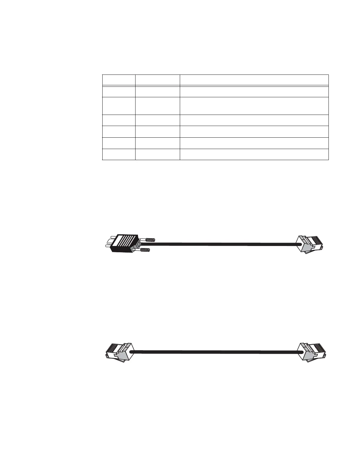
RJ-12 modular jack to micro DB-9 cable
The cable connecting the SPS to the SP management module is an RJ-12 to micro DB-9
cable (plug). It has an RJ-12 connector (SPS side) on one end and a micro DB-9 connector
(SP management module side) on the other end. Figure 16 shows an example of an SPS to
SP management module cable.
Figure 16 Example of SP management module (micro DB-9) SPS (RJ-12) cable
RJ-12 modular jack to RJ-12 modular jack cable
The cable connecting the SPS to the LCC is an RJ-12 to RJ-12 connector. It has an RJ-12
connector (SPS side) on one end and a RJ-12 connector (LCC side) on the other end.
Figure 17 shows an example of an SPS to LCC cable.
Figure 17 Example of LCC (RJ-12) to SPS (RJ-12) cable
Table 10 SPS (RJ-12) connector pinout
RJ-12 pin Signal name Description
1 Ground Signal reference
2 Enabled_out SPS is enabled and ready for On-Battery operation when
needed.
3 AC_fail_out AC line fallen out-of-spec.
4 Any_fault_out Fault state exists within the SPS.
5 SPS_TX Transmit signal out of SPS to host processor
6 SPS_RX Receive signal into SPS from host processor
VNX-000283
DB-9
RJ-12
RJ-12RJ-12
VNX-000569

 Loading...


