30 EMC VNX8000 Hardware Information Guide
System component description
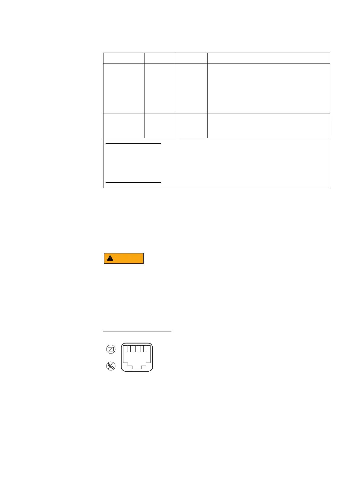
SPS RJ-12 connector
Figure 15 shows the SPS (RJ-12 or modular jack) management port (labeled with two
symbols; one depicting a telephone handset with a line through it and the other depicting
a rectangle with a line through it). Both symbols mean that you cannot connect telephone
type circuits to this connector (see the following WARNING). This port connects the SPS (A
and B) to the SP (A and B) RJ-12 ports or to the LCC (A and B) RJ-12 ports, respectively.
The SPS (RJ-12) port is a LAN port not a WAN port. LAN ports contain safety extra-low
voltage (SELV) circuits, and WAN ports contain telephone-network voltage (TNV) circuits.
An RJ-45 (or TNV-type) looks the same as the RJ-12 except for two very important
differences. An RJ-45 is an 8-wire modular jack. The RJ-12 is a six-wire modular jack. The
RJ-45 plugs and jacks are wider than their RJ-12 counterparts - 7/16" vs 3/8". An RJ-45
plug won't fit into an R-J12 jack. But an RJ-12 plug will fit into an RJ-45 jack. Use caution
when connecting cables. To avoid electric shock, do not attempt to connect TNV circuits
to SELV circuits.
Figure 15 SPS RJ-12 port
SPS no battery Amber On SPS battery is not fully charged and might not be
able to serve its cache flushing function. With the
battery in this state, and no other online SPS
connected to the SP, the system disables write
caching, and writes any modified pages to the disk
first.
Replace the SPS as soon as possible.
SPS internal
fault
Amber On The SPS has an internal fault. The SPS might still be
able to run online, but write caching cannot occur.
Replace the SPS as soon as possible.
Note: When the SPS powers up, all the LEDs go through a test sequence. They will first turn on and
then turn off beginning with the SPS power on LED (green) ending with the SPS fault LED (amber).
Each LED will light for one second and then turn off. After this sequence, normal LED operation
begins. If the AC line voltage is out-of-specification at power up, no LEDs will light until the AC line
voltage is within specification.
Table 9 SPS LEDs description (continued)
Led Color State Description
VNX-000626

 Loading...


