System component description
EMC VNX8000 Hardware Information Guide 37
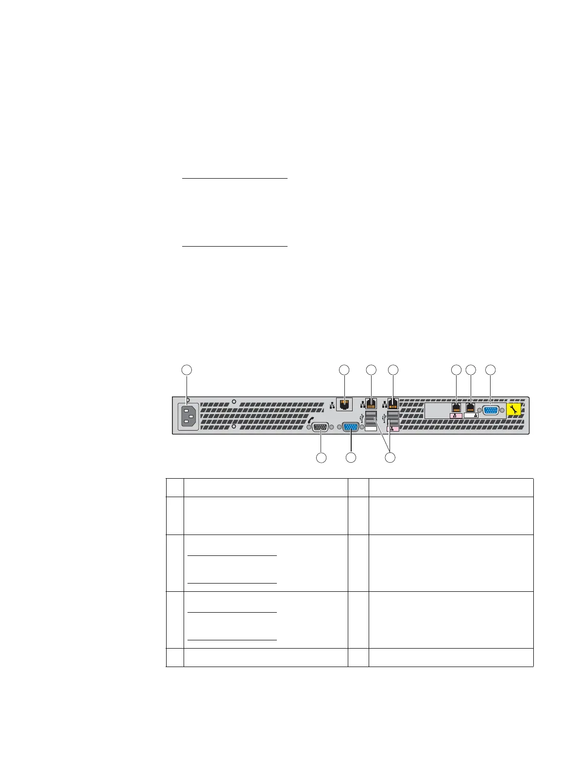
Control Station rear view
On the rear, viewing from left to right, the File/Unified VNX8000 platform Control Station
includes the following components:
◆ AC power in connector
◆ Five (RJ-45) connectors (labeled A, CS, B, and two MGMT [one not used, see location 2
in Figure 23])
Note: The RJ-45 connectors (labeled CS and A, respectively) are integrated into the
rear of the 1U Control Station while the RJ-45 connectors (labeled B and MGMT,
respectively) are on a PCI-e card in the expansion slot on the rear of the Control
Station. The fifth RJ-45 connector (labeled MGMT) is located to the left of the RJ-45
connector labeled CS. Newer CS models have a dust cover in this port.
◆ One (DB-9 plug) serial (RS-232/EIA-232) connector
◆ One (DB-9 plug) modem (RS-232/EIA-232) connector
◆ One (DB-15) video (VGA socket) connector—not used
◆ Four USB 2.0 connectors—not used
Figure 23 on page 37 shows the orientation of these components.
Figure 23 Example of a VNX8000 Control Station (rear view)
1 AC power in connector 6 RJ-45 Ethernet port (labeled MGMT)
2 RJ-45 Ethernet port (labeled MGMT), not
used; newer CS models have a dust cap in
this port
7 DB-9 serial console plug connector
3 RJ-45 Ethernet port (labeled CS
1
)
Note: The CS label is located below the
USB ports.
1. The CS port uses an IPMI (Intelligent Platform Management Interface) cable to connect to a standby (optional)
Control Station (CS1).
8 Four USB 2.0 connectors (not used)
4 RJ-45 Ethernet port (labeled A)
Note: The A label is located below the USB
ports.
9 DB-15 Video (VGA) socket connector (not
used)
5 RJ-45 Ethernet port (labeled B) 10 DB-9 modem plug connector
B MGMT
MGMT
B
CS
A
1
2
MGMT
IOIO
2
3
4 51 6
89
10
7
VNX-000525

 Loading...


