36 EMC VNX8000 Hardware Information Guide
System component description
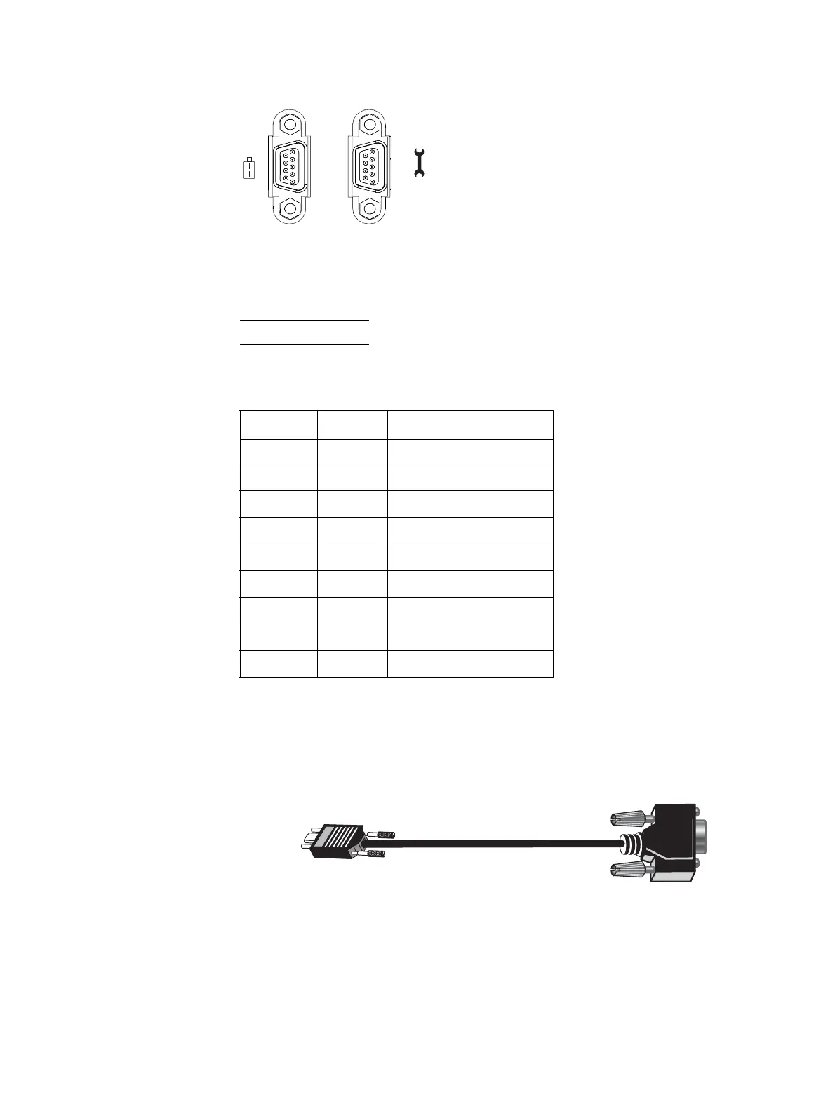
Figure 21 SP management module serial console (DB-9) socket connectors
Table 12 lists the SP management module Ethernet (DB-9) pin signals used on the
connectors.
Note: The pin designations shown in Figure 21 are for reference only.
Storage processor null modem (micro DB-9 to DB-9 serial) cable — The cable connecting
the SP management module to the PC or service laptop is a micro DB-9 cable (plug) to
serial DB-9 (socket). It has a micro DB-9 plug (SP side) on one end and a serial DB-9
socket (PC or service laptop side) on the other end. Figure 22 shows an example of an SP
management module to PC (service laptop) cable.
Figure 22 Example of SP null modem (micro DB-9) to serial (DB-9) cable
Pin 1
5
9
6
Pin 1
5
9
6
Table 12 SP management module (DB-9) socket connector pinout
DB-9 Pin Signal Description
1 CD Carrier detect
2 TXD Transmitted data
3 RXD Received data
4 DTR Data terminal ready
5GNDGround
6DSRData set ready
7 RTS Request to send
8 CTS Clear to send
9 RI Ring indicator (not used)
VNX-000093

 Loading...


